Back to homepage
Simple square wave and pulse generator
A.K.A. 1960-ies style guerilla homebrew 6 Hz - 2 MHz function generator
with 4 transistors :)
Introduction
Recently I needed a function generator for the workshop at the place where I work.
Detailed inspection showed that we had four.

One is in good shape, made in 1979, and capable of producing sine, triangle and square waveforms.
This one is retained and used as main function generator for testing purposes
at my main workshop location.

Other three were not working, or working sporadically.
They were all from 1950-ies or early 1960-ies, with vacuum tubes, of two different
types.
High voltage was ok on all of them, but output was lacking or intermittent.
I decided to scrap them, keep the working tubes, transformers and metal for future projects,
and make a new function generator using only transistors.
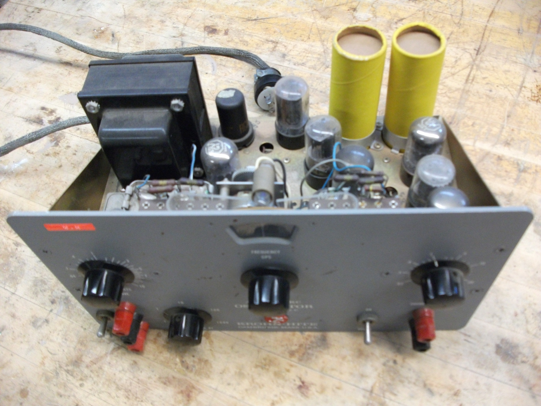
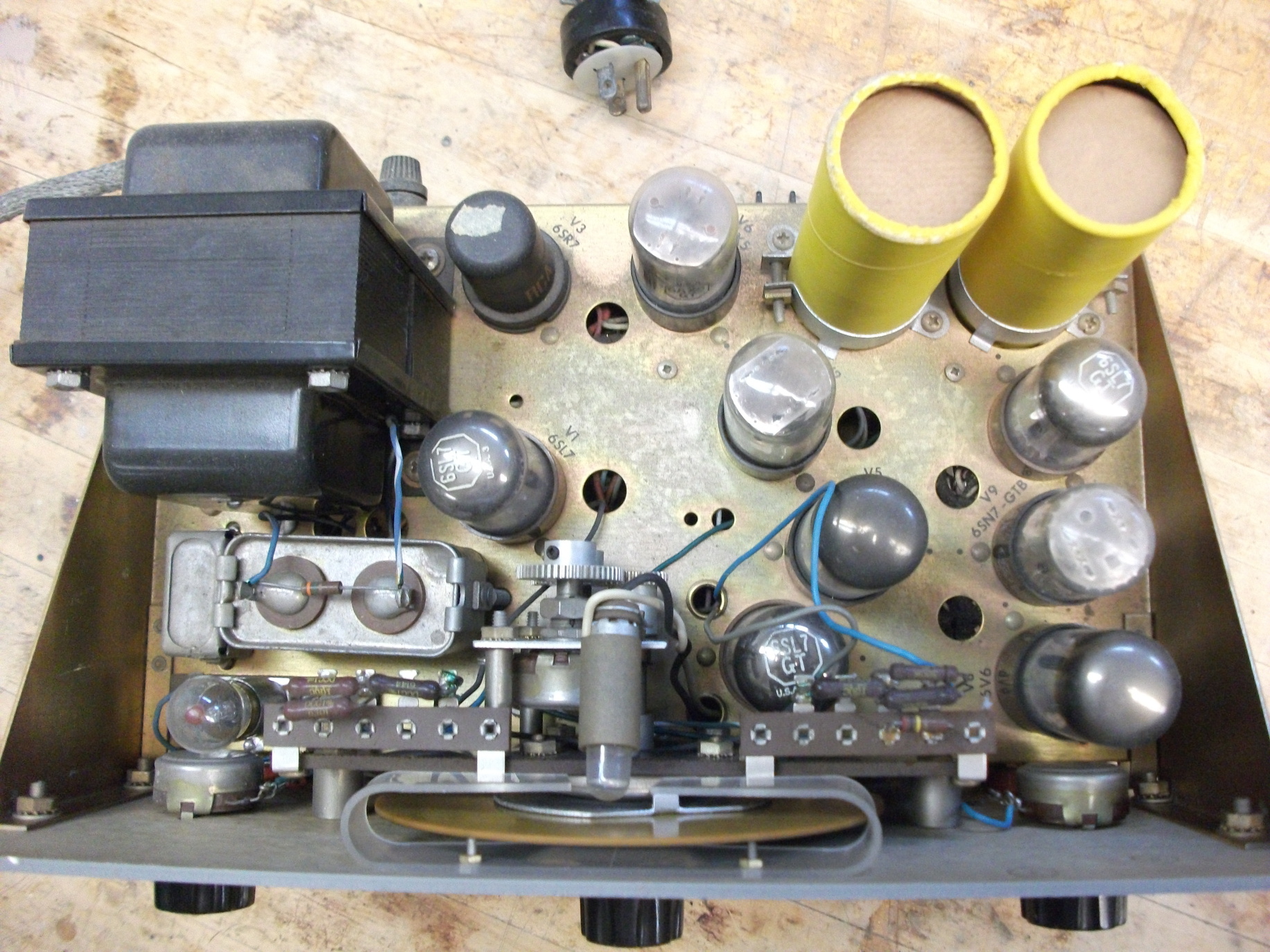
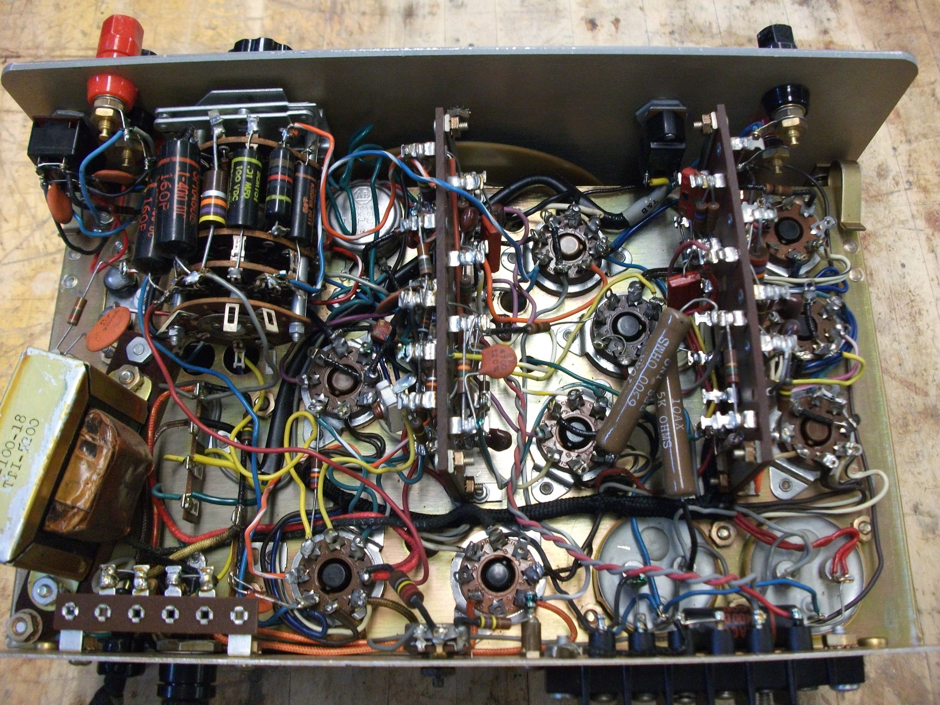
Old vacuum tube based function generators
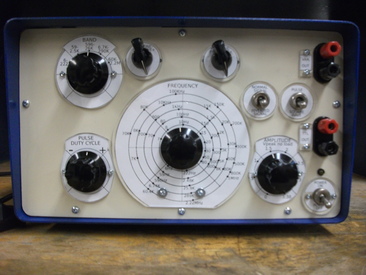
Old Krohn-Hite function generator images. Two non-working examples were found.
They were of very solid build. Useful parts were kept for future builds.


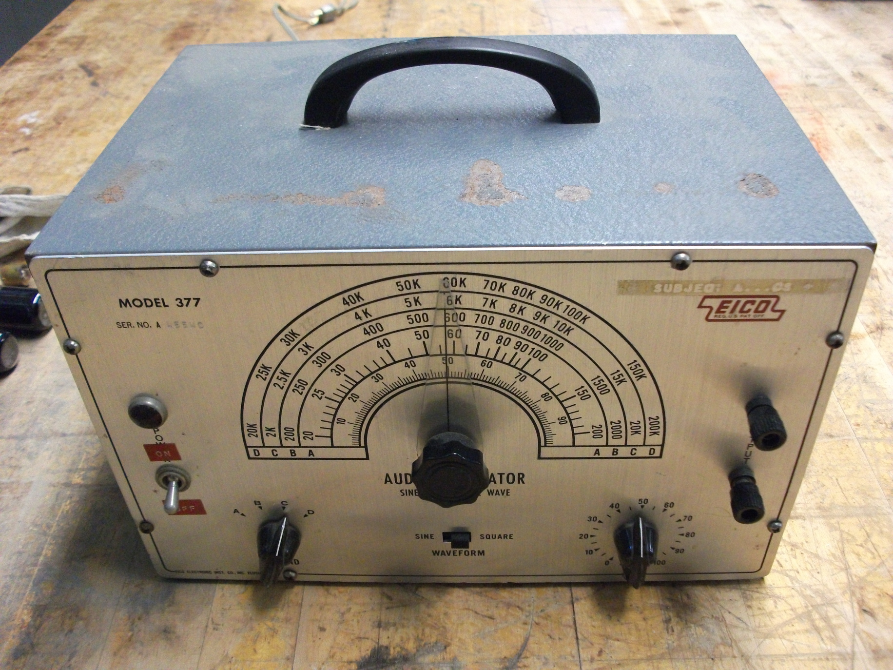
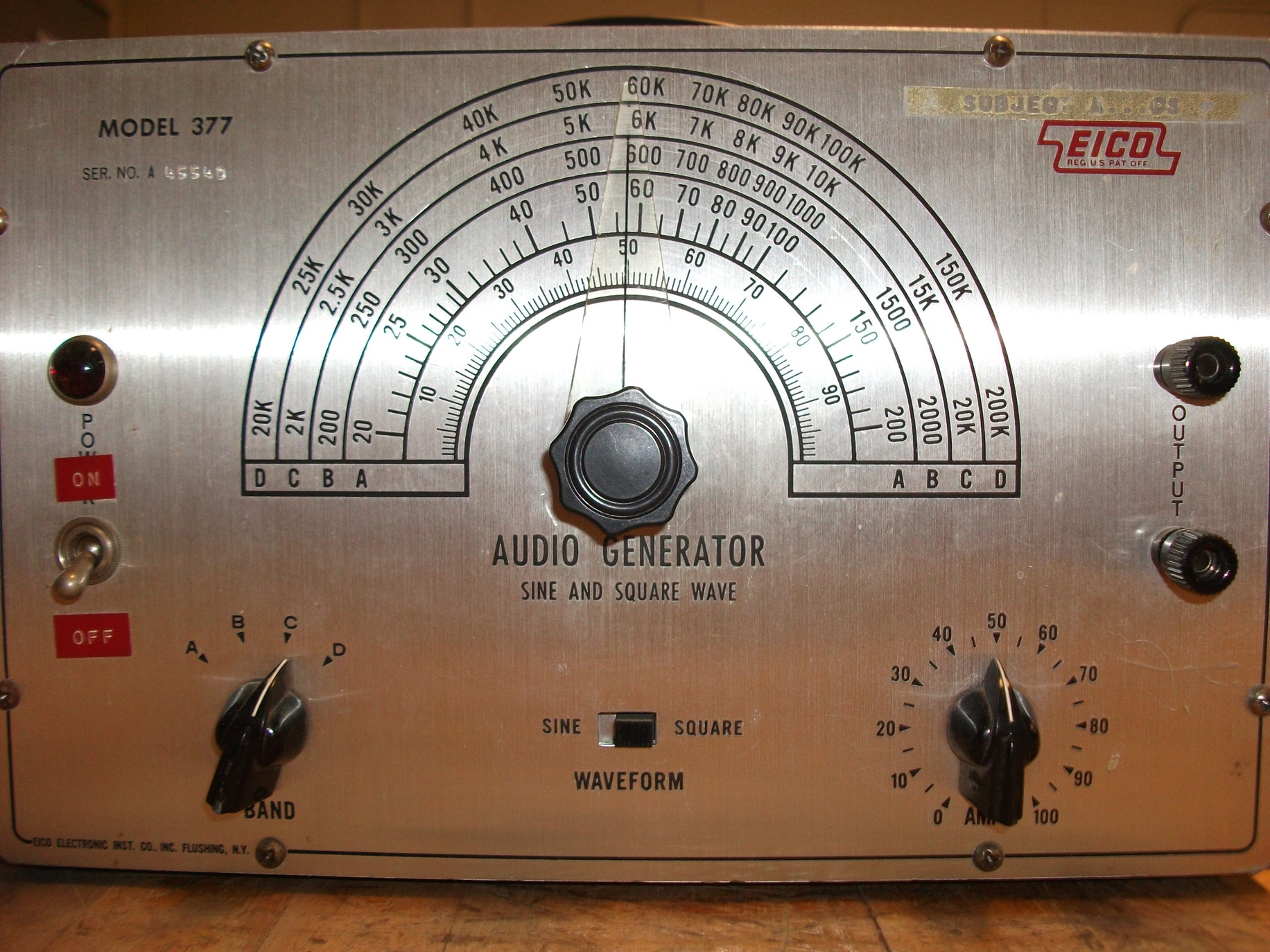
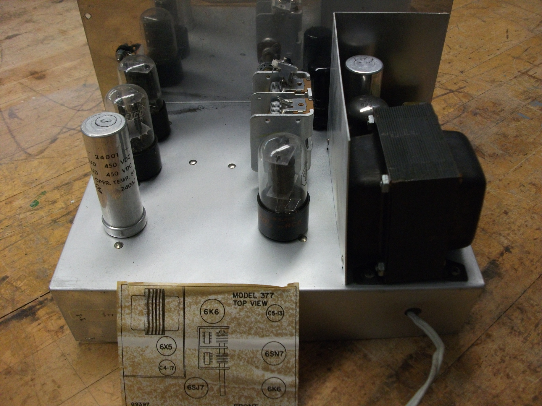
Old EICO function generator. Much poorer workmanship quality, thin steel chassis plates, etc.


Transistors only? Why?
New generator was supposed to have all the bells and whistles, and use case and if possible
other parts from the scrapped vacuum-tube generators.

Transistor-only design might seem strange at this day and age.
However, I wanted to challenge myself.
And there was another, somewhat nostalgic reason:
I have spent some years in a war zone, and I can appreciate how difficult it is to extract chips
from boards (and get their datasheets) during times of war.

Transistors were easily removed from equipment, and were not critical when in different role.
BC108 will work just as well as 2N2222 in a LF amplifier for instance -
often without any change in external components.

Therefore, transistor design has a practical second and third world use,
IC based one much less so.

No special chip? Tough luck.
It's not going to arrive on a mortar round.
So, for all the people in the world that are maybe now in the similar situation that
I was some 25 years ago, it is going to be a simple and reliable, no frills build.

Plus if you are prepper ... you will be in a similar situation when SHTF.


Use of a voltage regulator IC is not cheating.
Device works perfectly well without it, frequency is just more stable with regulator.
Frequency drift using unregulated power supply is only 2-3 %.
Frequency drift with 5 V voltage regulator, measured in a 24 hour run, is always less than 1%.
And anyway, 78L05 is a three terminal device :)


Complaint that's more to the point is the dual rotary switch with 5 positions.
If you can't find it, you can use regular DPDT switch for two bands only.
Bands can be "stretched" by using smaller band shortening fixed resistors
(1 Kiloohm in my schematic).

This will increase total ratio of resistance change and provide wider range (and coarser) tuning.
Other option is to use Megaohm dual-ganged base resistors with Darlingtons instead of regular transistors.


With those measures, it is possible to achieve say 10 Hz - 1 KHz band A and 1 KHz - 100 KHz band B.

No DPDT switch / just lazy you say?
Use one band only and you don't need a switch at all ...

You have no dual-ganged resistors?
Ok, just find two regular potentiometers.
Your tunning will now involve adjusting 2 pots, but that is a small price to pay for a
working function generator, if nothing else is available.

Nothing else in this schematic is critical: change transistors, supply voltages,
resistors, capacitors. It will work with a very wide range of components.
Sinewave and squarewave generators
For several weeks, when time permitted, I was testing different configurations
of sine and square-wave oscillators.
They all had some advantages and shortcomings.


Phase shift oscillator: narrow frequency range (1:2), meaning I would not be able
to have continuous wide frequency coverage.

Wien-bridge oscillator:
I tried two different transistor based designs and they only worked well in narrow range,
and there was a number of other problems.

Gain had to be set to little above 3 initially and then lowered to 3 for the least
amount of distortion.

A small lightbulb was often used in the past to provide changing resistance for gradual
gain reduction.
Resistance of the bulb would increase after the power is applied,
decreasing positive feedback and gain.


LC oscillators: really hard to use at lower frequencies.
And your 500 picofarad variable cap is not going to change much of a frequency when connected
to a large 100 mH coil. So a variable coil is needed.

LC oscillators are excellent for radio range though.
Astable
multivibrator: produces square waves and pulses, easy to get to
work, stable and works with wide variety of voltage supplies and
frequencies. No sinewaves though.
After some thinking and experimentation, I found out that I will have too many dials and controls
brought out if I use both square wave and sinewave oscillators.

Therefore I decided to use square wave oscillator (astable multivibrator) only,
but provide it with all the controls I might possibly need.
Pulse generation, fine Ton/Toff regulation and frequency adjustment are easily added.

Total period of oscillation is equal to T=Ton+Toff, where Ton and Toff can be easily manipulated
with a potentiometer.
Periods are function of connected resistance and capacitance.

If sinewave is really needed, it can be had by filtering the output to supress all harmonics.
But I do hope to build a pure sinewave oscillator when time permits, in a separate metal case,
saved from second tube generator.
Astable multivibrator is selected
After consulting "Transistor manual" (General Electric 1964) and the internet,
I finalized my circuit testing.

Collector resistors were set to 2.2 Kiloohms, base resistors to dual-ganged 100 Kiloohm
potentiometer (frequency adjustment) in series with current limiting
(and frequency range shortening) 1 Kiloohm resistors.

One additional (on/off switched) 500 Kiloohm potentiometer,
in parallel with one 100 K dual-pot section is used to regulate pulse width,
if pulses are desired instead of square waves.

Very fine tuning is achieved with 2.5 Kiloohm pots. There are 5 frequency ranges,
two capacitors are switched for each range.
Values are 100 pF, 1 nF, 10 nF, 100 nF and 1 microF ceramic.

This provides 6 Hz - 2 MHz range of possible frequencies in 5 ranges.

Transistors as originally used: 2N4401 - dirt cheap general purpose NPN
silicon transistors.

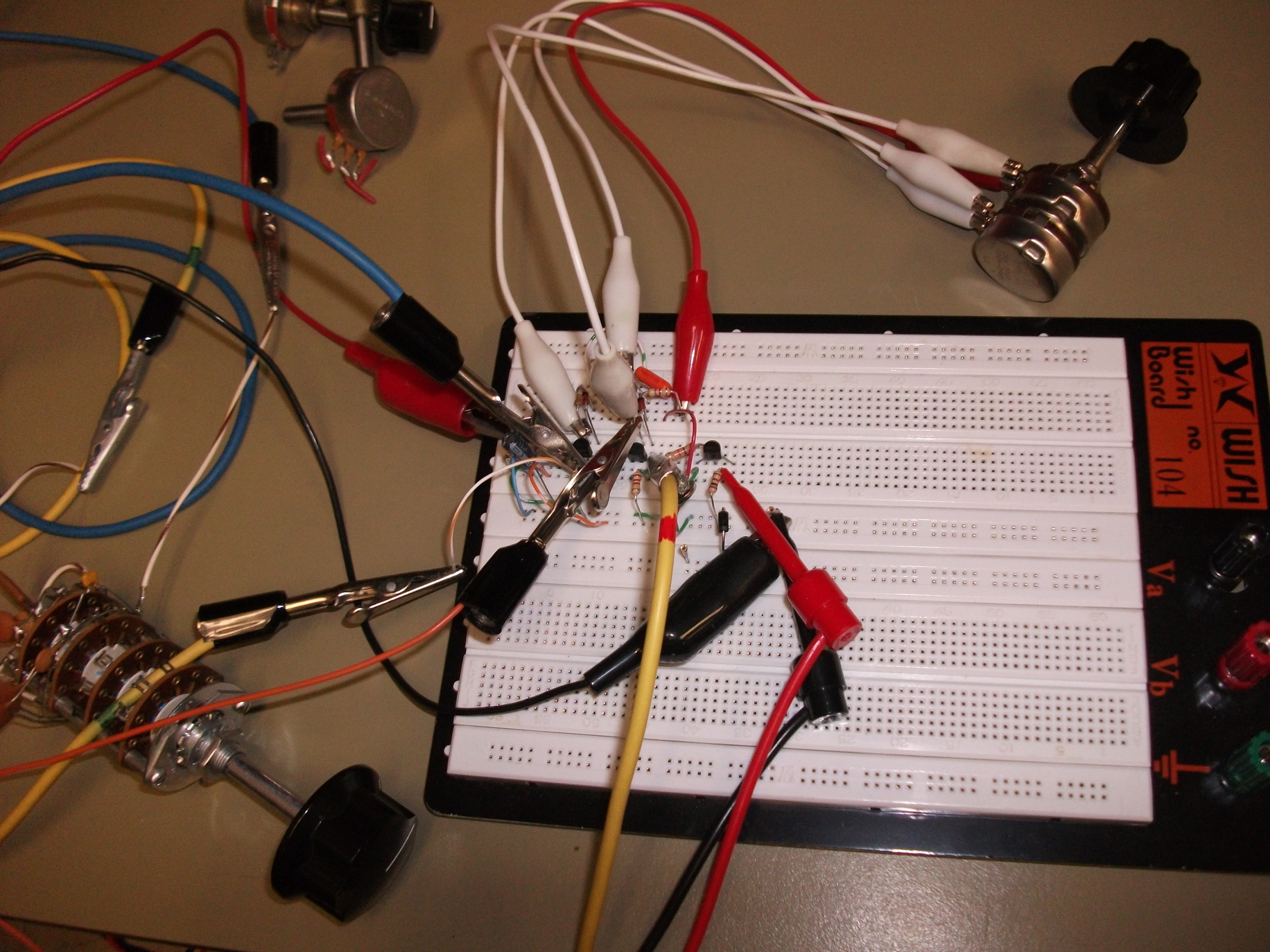
Initial protoboard testing. Also visible: dual potentiometer (frequency tuning) and
rotary capacitor switch (frequency range selection).
Output can be picked from either multivibrator transistor collector (normal/inverted) and is then
fed to a TTL stage which outputs TTL level signal (TTL OUT).
Variable signal level is available on the VAR. OUT connectors.
Schematic
Top part of the schematic is a power supply.
Transformer provides 12 Vac on the secondary.
Half-wave rectifier is used because of small current drain and voltage regulator.

If voltage regulator is not used it would be better to have a full-wave rectifier or,
failing that, large electrolytic capacitor in the filter stage.

Transistors are labeled as follows:
T1 - multivibrator transistor 1
T2 - multivibrator transistor 2
T3 - buffer and TTL level output driver
T4 - variable output driver

Transistors T1 and T2 are forming standard astable multivibrator.
Frequency band is selected with rotary switch that connects 2 capacitors at the same time.

Frequency tuning is done with dual-ganged 100 Kiloohm potentiometer.
Fine Ton/Toff and (at the same time) frequency tuning is done with two 2.5 Kiloohm potentiometers.
500 Kiloohm potentiometer is used to adjust the pulse width if square wave/pulse switch
on the front panel is closed.

1N914 diodes serve to improve the sharpness of the square wave.

T1 and T2 collector resistors are as small as possible, but have to be larger than Rbase/Gain,
in order to ensure transistor saturation.
For example, if base resistor is 100 Kiloohms, and transistor gain is 50,
collector resistor of minimum 2 Kiloohms must be used (and that's pushing it).

T3 is buffer/TTL driver stage, with small collector resistance for fast switching.

T4 is added driver stage for variable voltage output.
It is connected after the TTL stage to reduce loading on multivibrator transistors.
This provides somewhat worse rise/fall times for T4 versus T3 however.
Build
There were a number of problems with the build.
Initially, no oscilloscope was available except for the venerable Tektronix 502A from 1963.

Newer Tektronix TDS 2002 from 2005 died in 2010. Display unit failed -
Tek asked $550 for replacement display unit. No way I was going to pay for that.

Rigol DS1052E ($399) was ordered late into the build.
Old 502A has a bandwidth of only 1 MHz (and it was heavily out of calibration),
so it was used only as a partly-trusted temporary help.

Parts soldered onto printed circuit board. Wires were eventually
shortened considerably.

Venerable Tektronix 502A provided useful service during the first part of testing.
However it was severely limited by its 1 MHz bandwidth.
This would cut-off square-wave harmonics at high frequencies and provide incorrect
waveform display.
With all this in mind, it was able to show to some extent what improved square wave shape -
and what did not. This was especially true at lower frequencies, below 100 KHz.
Initial testing with 502A scope showed that waveform was distorted at fairly low frequencies.
I knew that scope was flaky but this was too much
(I compared the waveform with known good function generator).
Literature recommended replacing collector resistors to smaller values to improve parasitic
capacitance charge/discharge time.
This was done on T3 and T4 and reduced response time considerably.
T1 and T2 collector resistors could not be made much smaller than 2.2 K because
transistors would not saturate and multivibrator would cease to work.
It was also discovered (datasheet) that 2N4401 transistors have poor rise/fall times when
compared to 2N3904 transistors.
Also they required larger collector currents than 2N3904 to even approach similar rise/fall times.
2N4401 transistors were therefore swapped for 2N3904s,
with marked further increase in performance.
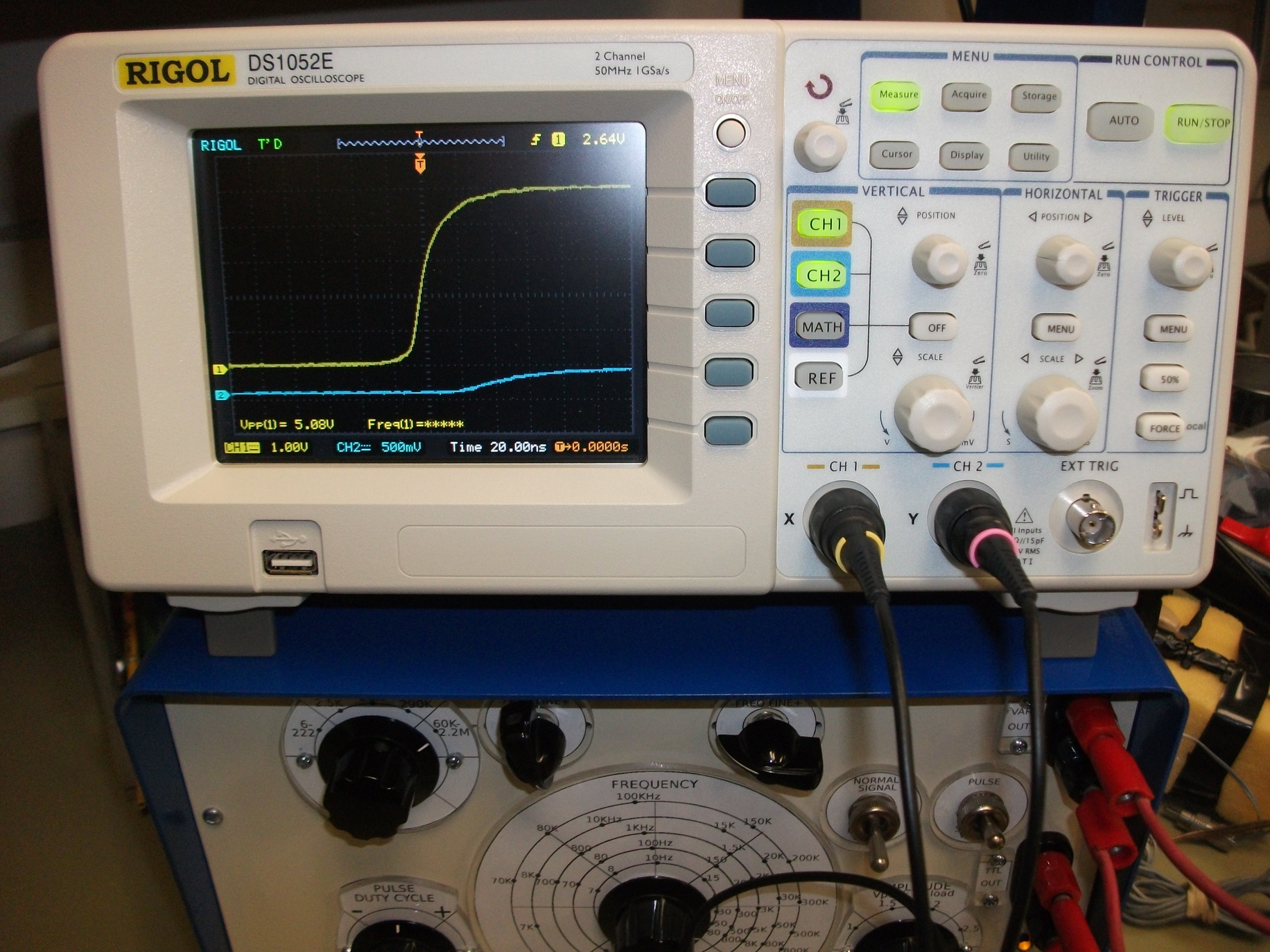
Some examples of gradual improvements to the waveform through the
change in components. Signal rise is shown much magnified.

Waveform with 2N4401 transistors.

Waveform with 2N3904 transistors.
After reading GE Transistor manual, it transpired that further increase
in switching speed can be gained by putting small capacitor in parallel
with base resistor for T3. This converts RTL
logic into RCTL logic :) Some improvement was seen.
Further tests revealed that 60 Hz noise was somehow modulated onto the
output signal, causing unacceptable behaviour especially around 25 Hz
area, and distortion elsewhere. After inserting a large 2200 microfarad
capacitor between +5 V and GND, problems disappeared. Original 10
microfarad capacitor was retained as well.
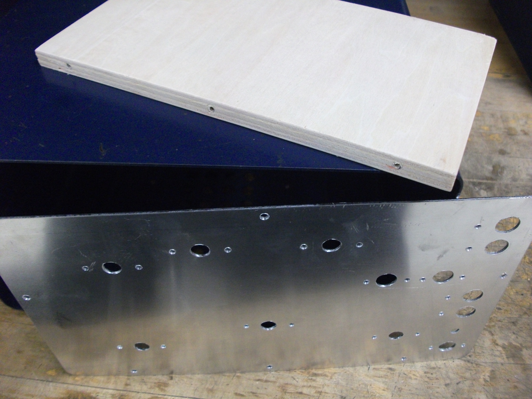
Case
Metal steel case was taken from old vacuum tube generator. It was
cleaned and painted. New PCB was mounted onto a piece of plywood.
Plywood piece also supports new front aluminum panel on the lower end.
Three wood squares were glued into the metal case to serve as
additional supports for the aluminum front panel. Front aluminum panel
shaft and screw holes have been drilled, after which the panel was
painted.

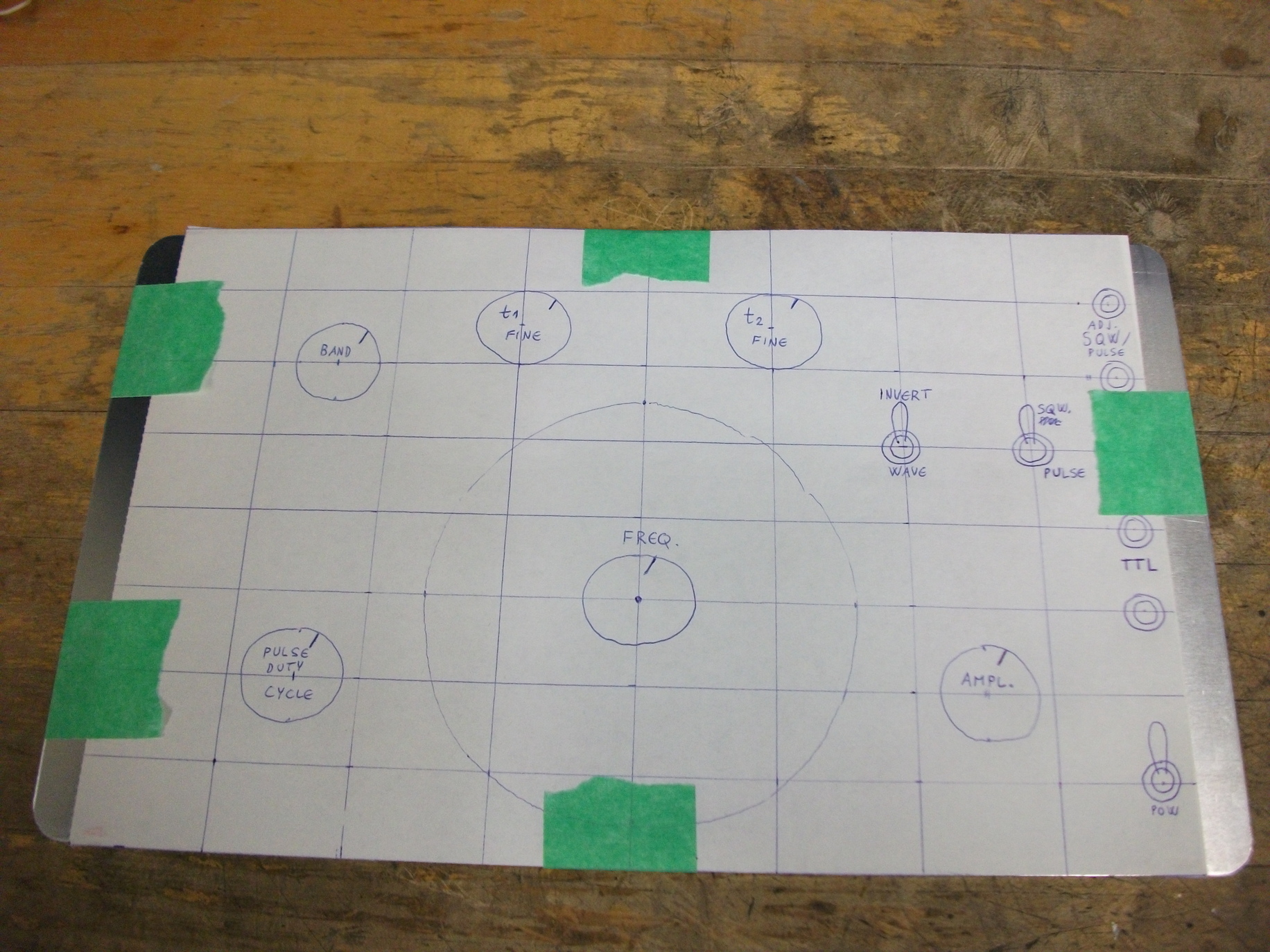
Template for front panel hole drilling.


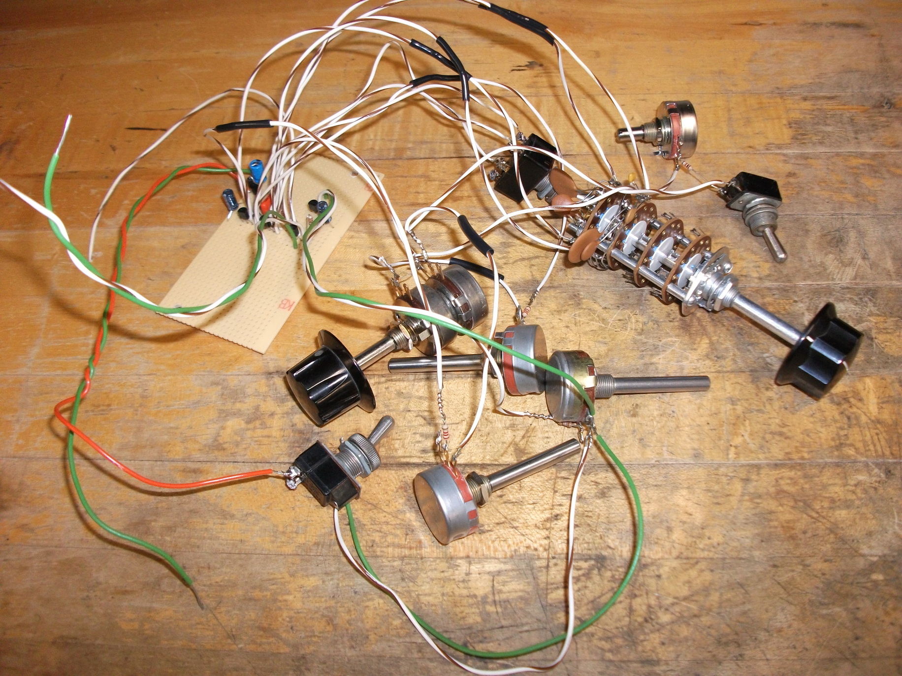
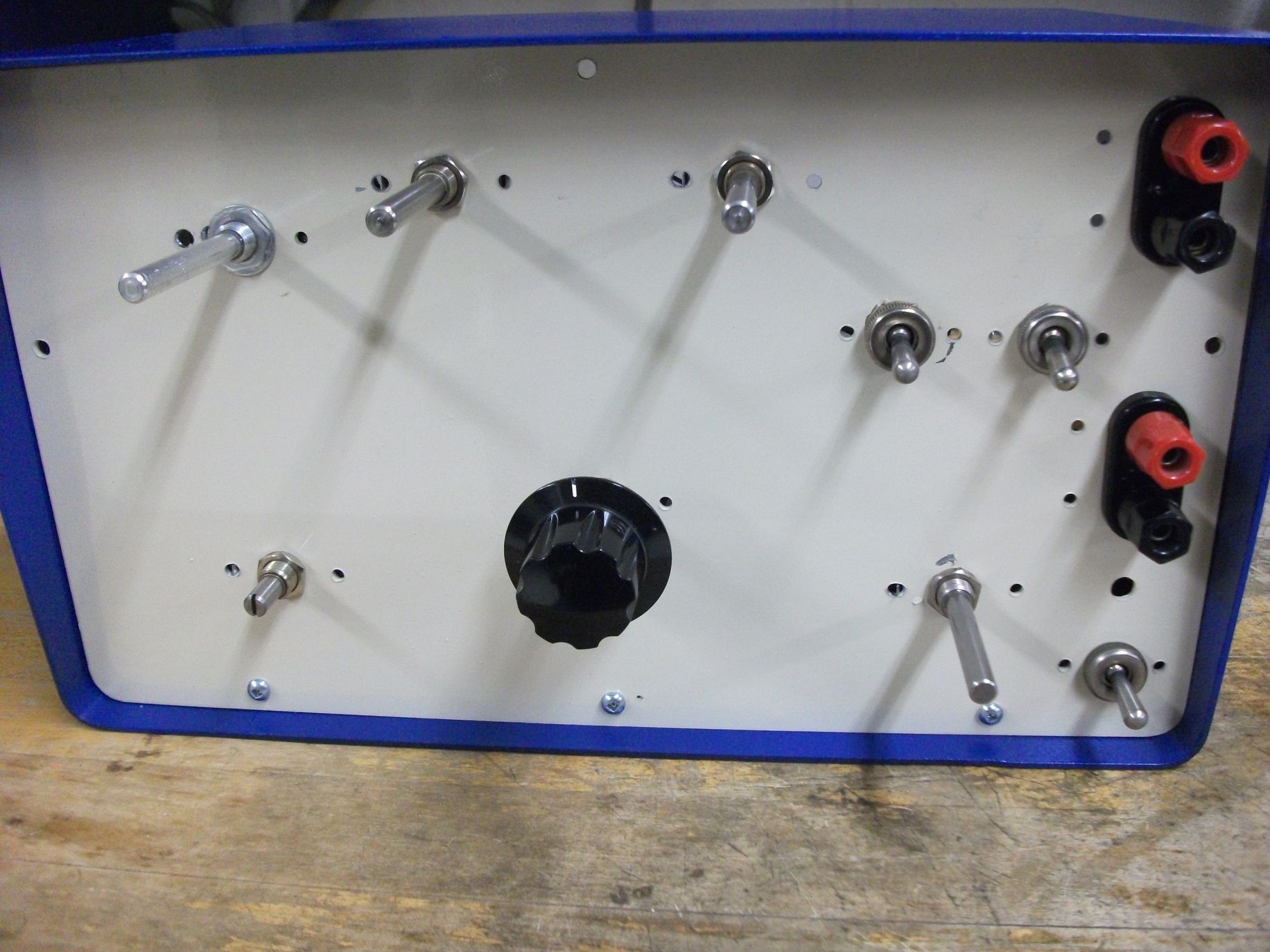
After case and front panel have been painted, potentiometers, switches
and other components were mounted for trials. They were removed few
times during the build, when needed. Potentiometer shafts had to be cut
down to size.
Dials, scales, calibration
Dials (knobs) were taken from scrapped tube generators.
Scales were a big issue: I wanted them to look nice,
but did not want to spend extraordinary amount of time on them.
But there was no easy solution and I went to a complicated solution eventually.
I did calibration with temporary circular piece of paper affixed to front panel.
Frequency was checked with frequency counter and counter equipped multimeter.
Each point was marked with a pencil.
Then a scale was drawn on a PC according to a temporary paper scale pencil marks.
I made each permanent scale in Inkscape, printed them, and cut them with scissors to fit.
Each scale also received a plexiglass (acrylic) plastic cover 3 mm thick to prevent damage
to the scale.
It took literally weeks to get all this right. Definitely not recommended for
mass production.
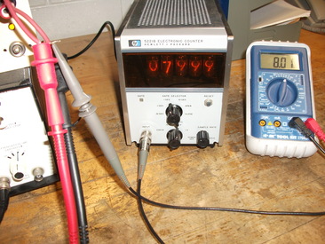
Old nixie-tube display counter and multimeter frequency meter were used
for calibration.
Finished product
Few pictures of the finished function generator are shown, with and without the case.
Case was salvaged from scrapped vacuum tube based Krohn-Hite generator and repainted.

Front panel without case.

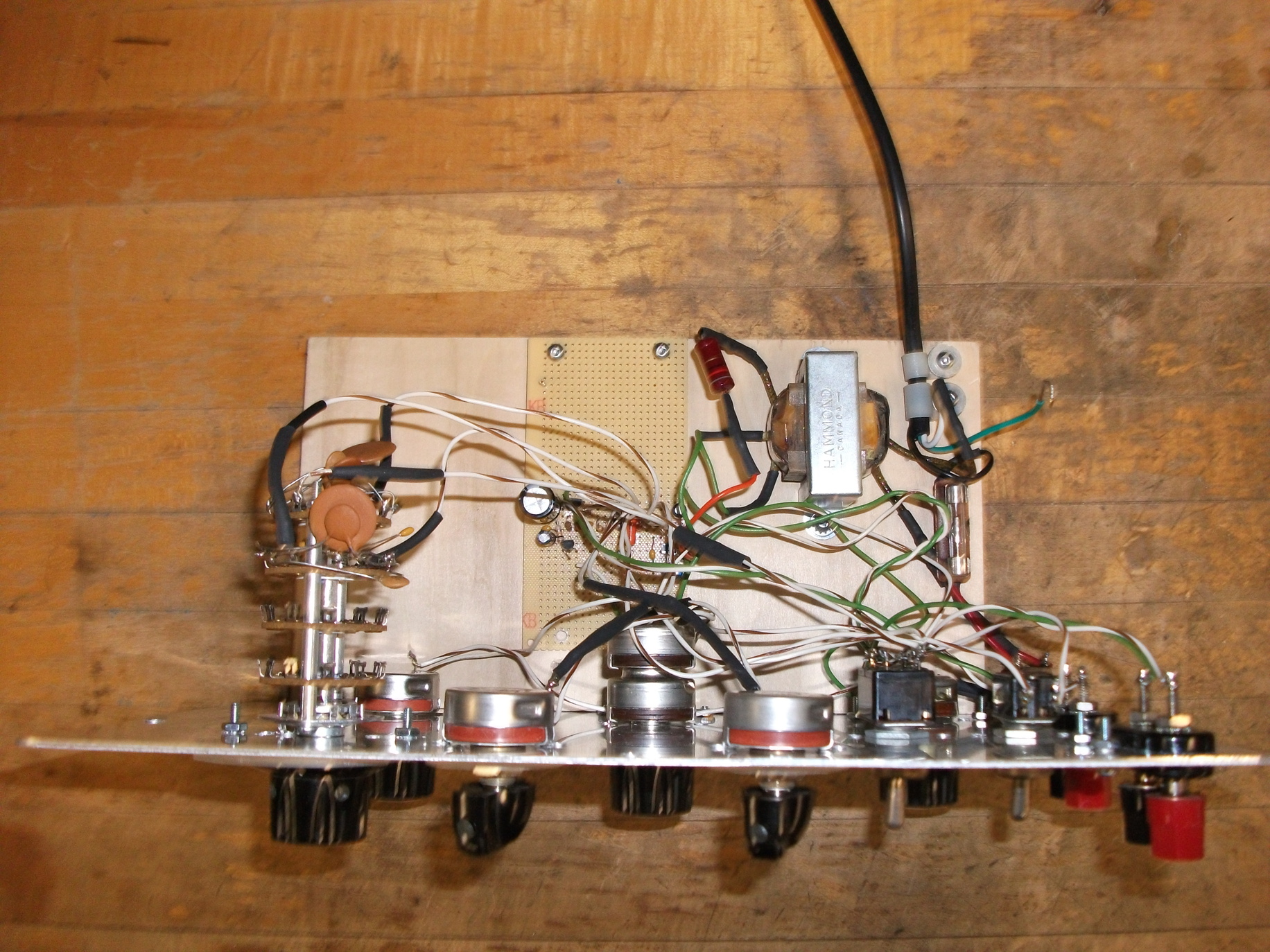
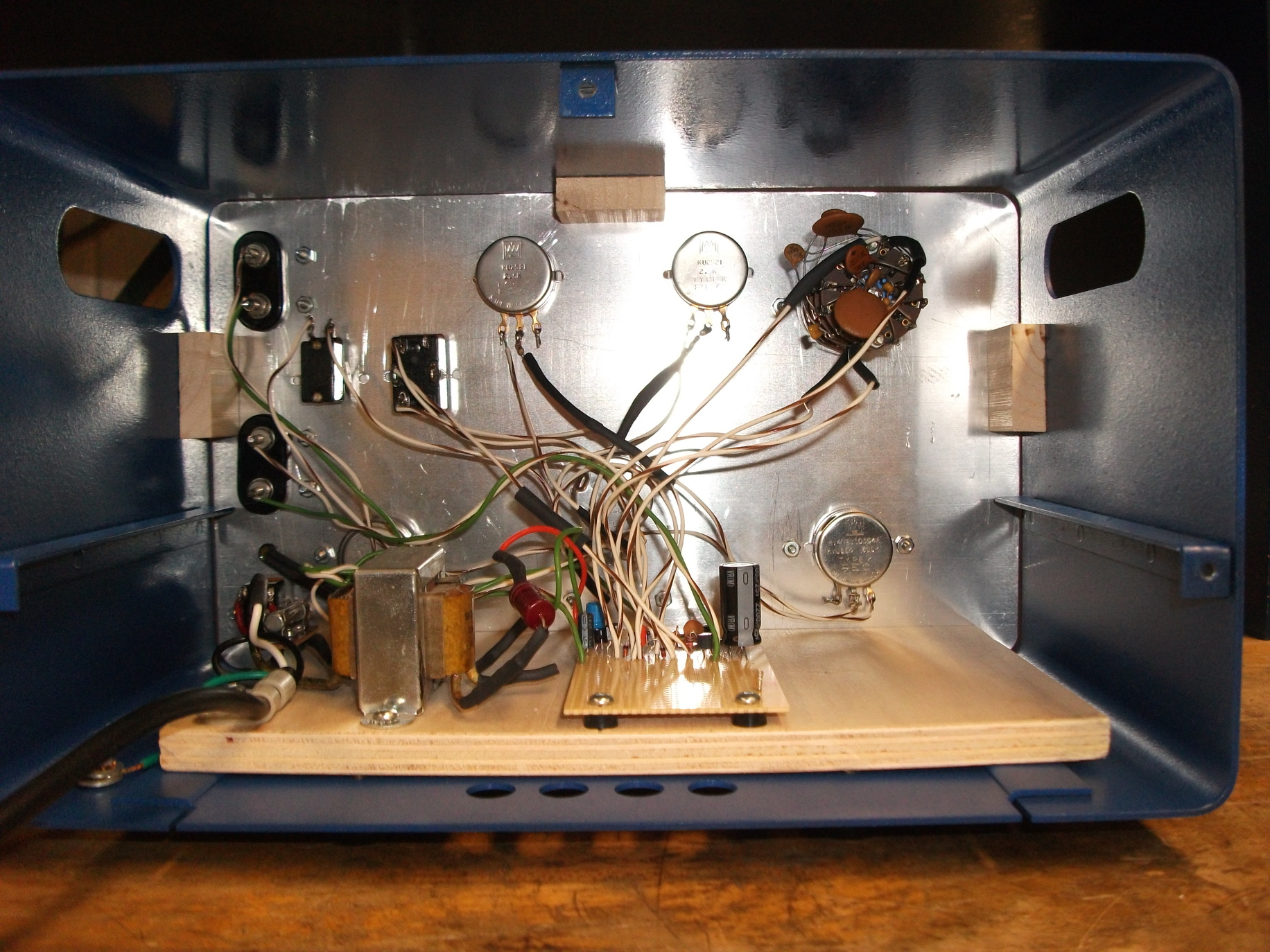
Top view without case.

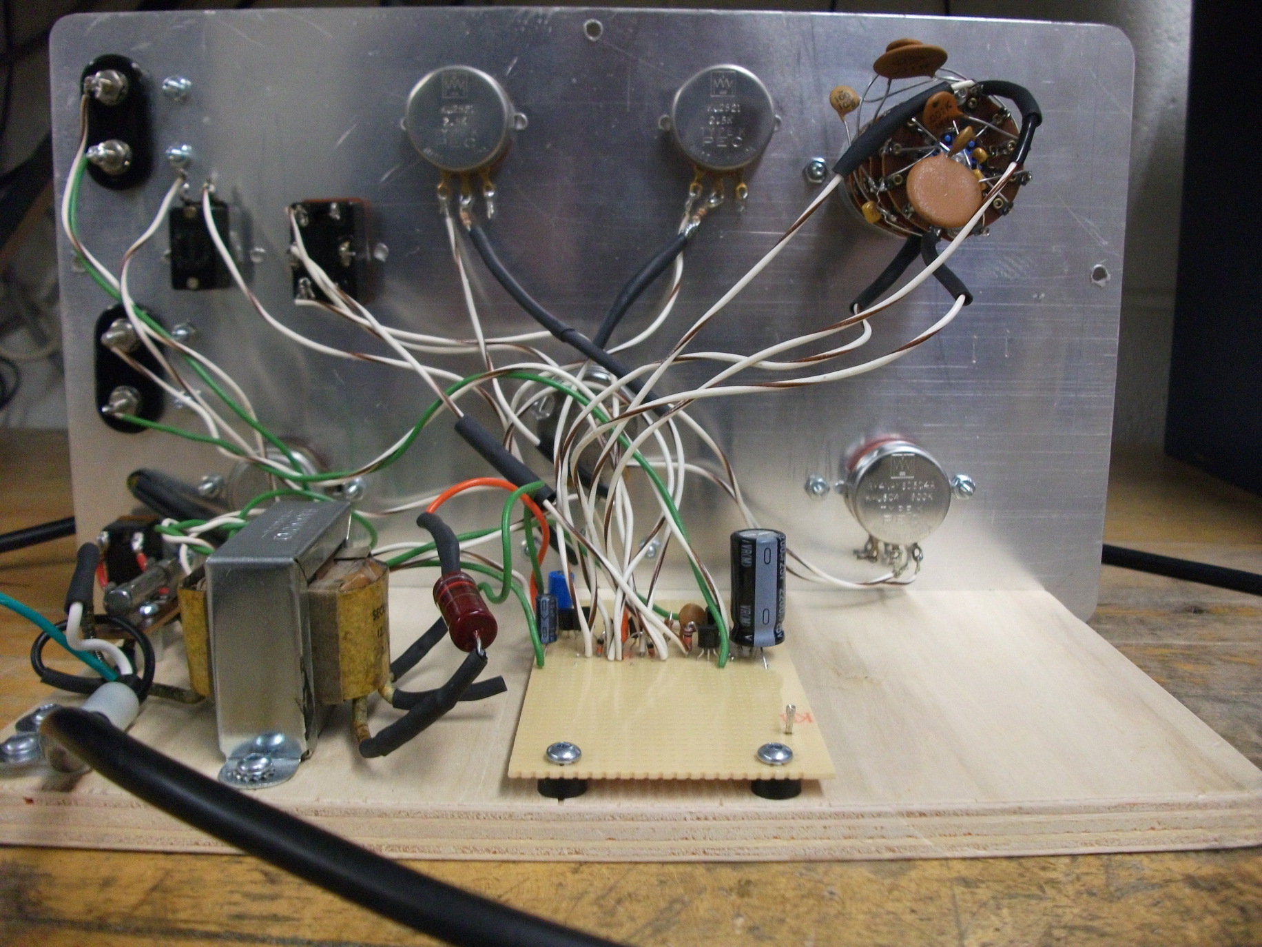
Back view without case.

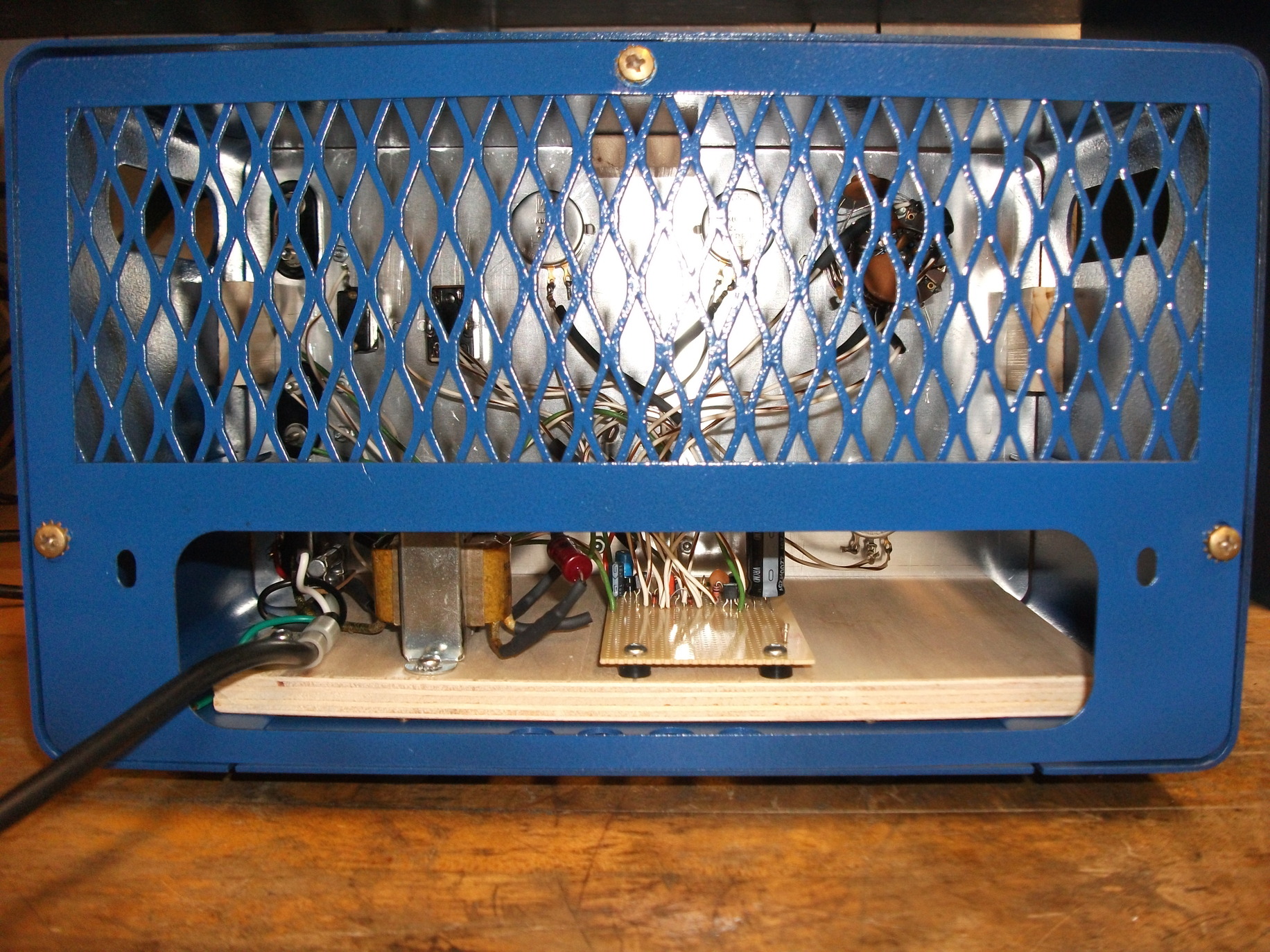
Back view with case.
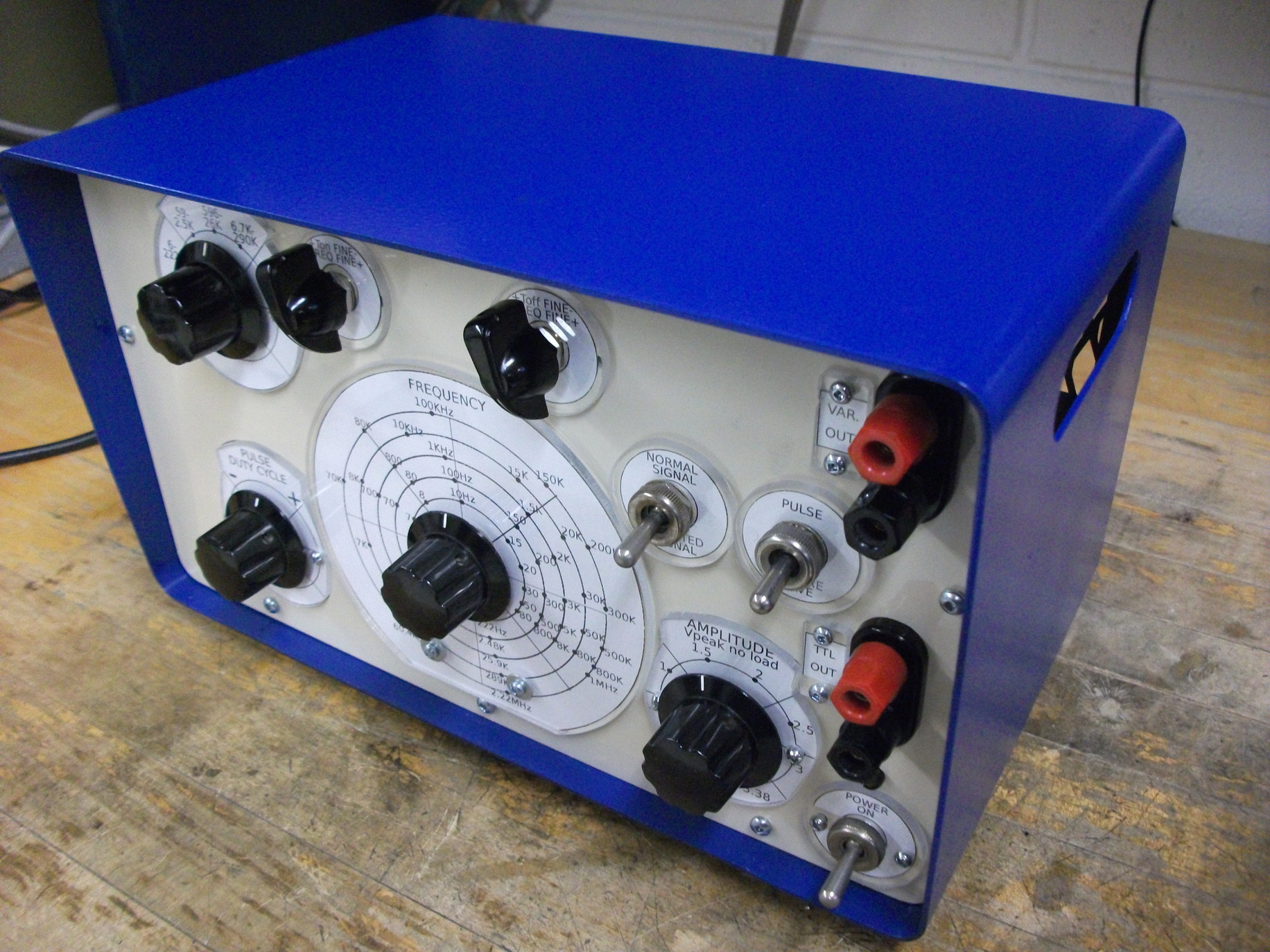
Front view with case.

Back view with metal cover on.

Angled front look.
Controls
Remark: T=Ton+Toff, T=1/f. T=period, f=frequency. Ton=pulse high, Toff=pulse low.
Controls are used to set:
1. Frequency of the square waves and pulses (scale calibrated for square waves only)
2. Five frequency bands. 6-222 Hz, 59-2480 Hz, 596-25900 Hz, 6.74-289 KHz, 60.4-2220 KHz.
3. Fine frequency adjustment 1 (in fact Ton duration)
4. Fine frequency adjustment 2 (in fact Toff duration)
5. Pulse duration (if pulse selected).
Variable from 1-49% (normal) and 51-99% (inverted) duty cycle
(maximum, when frequency dial is in leftmost position).
6. Output amplitude (VAR OUT connector). TTL OUT levels are unaffected by this.
7. Normal/inverted (selects either T1 or T2 collector for output to T3)
8. Square wave / pulse selection.
9. Power on/off.
Output: 5 V TTL levels and adjustable 0-3.38 V levels.
Use
Square wave generator is useful for many applications.
One of them is to quickly estimate a bandwidth of an amplifier
(square wave has infinite number of harmonics).
Second is distortion check. Non-ideal amplifier will distort the wave.
Third is keying of a test radio/infrared transmitter for example.
Particular use for variable-width pulse generation is severalfold:
pulse width modulation (PWM) for motor control,
infrared/laser/radar pulsing (time domain reflectometry),
response time measurement etc.
Performance and operation
6 Hz - 2 Mhz frequency range in five frequency bands.
Square wave and pulse, 1-49%, 51-99% (maximum, when frequency dial is in leftmost position).
TTL OUT voltage level, and variable voltage 0-3.38 V level out.
Around 40 nanosecond waveform rise time (from 10 to 90% of amplitude).
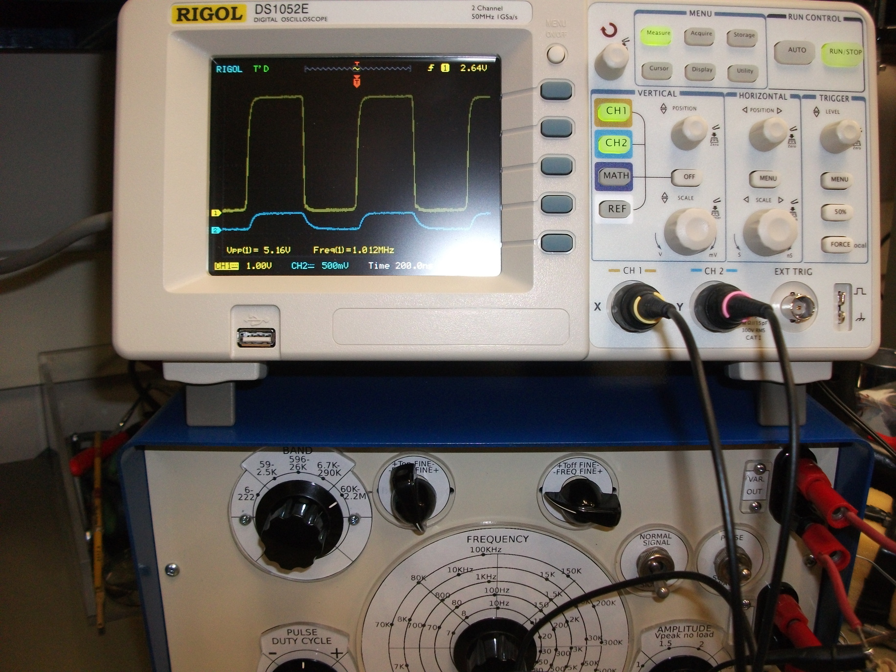
Some images of the unit in operation are shown.
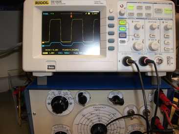
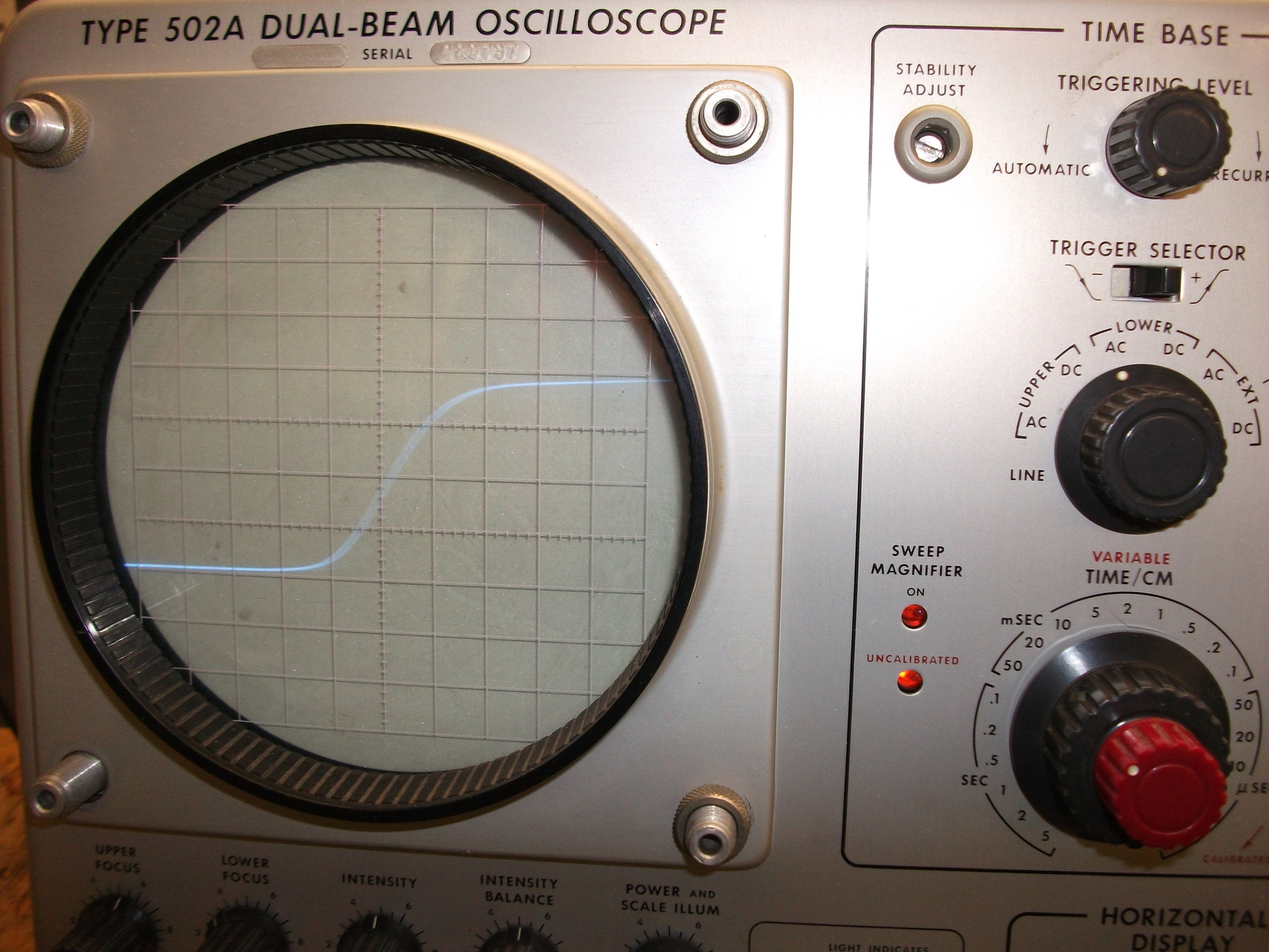
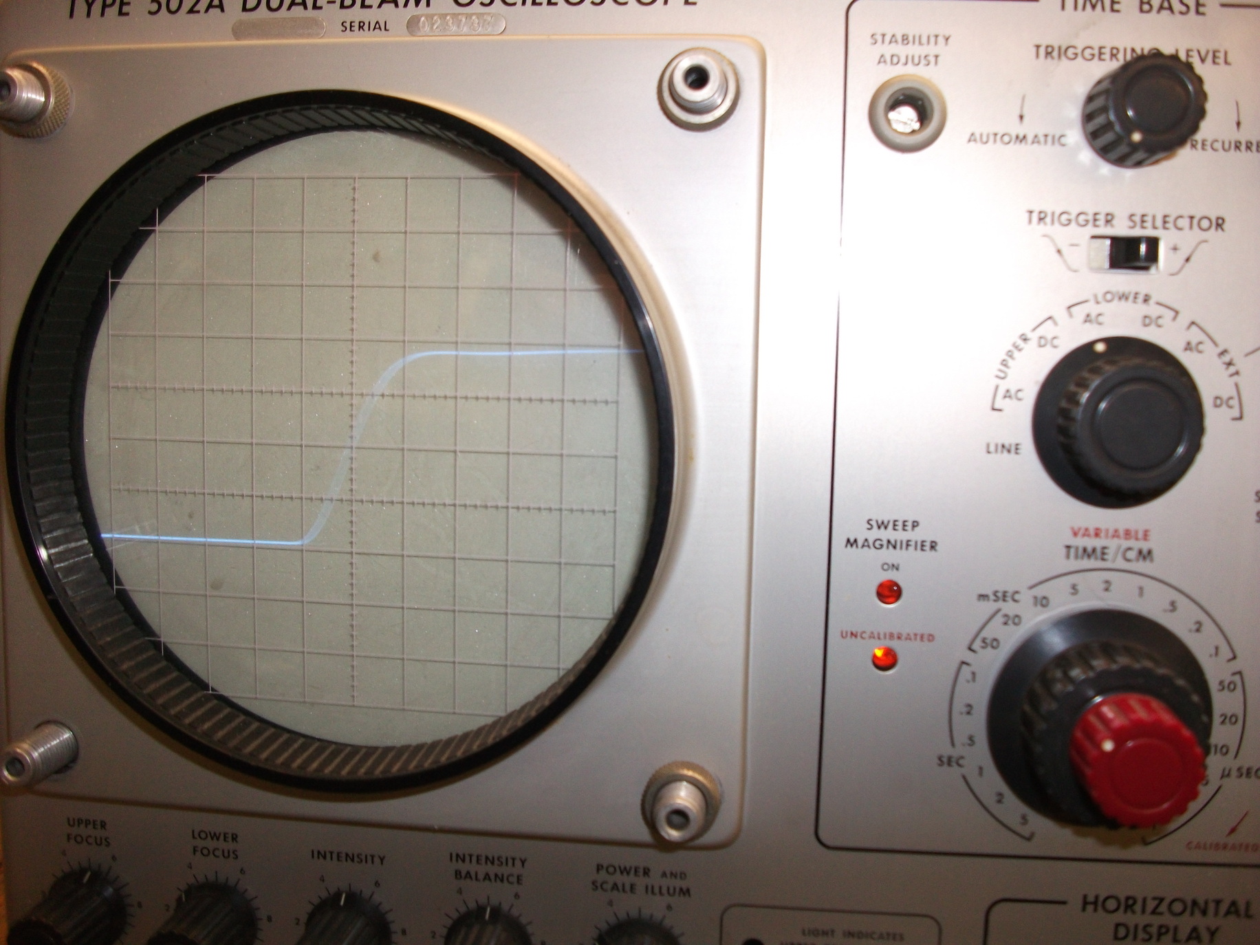
1 MHz operation is demonstrated.

Rise time is around 40 nanoseconds.

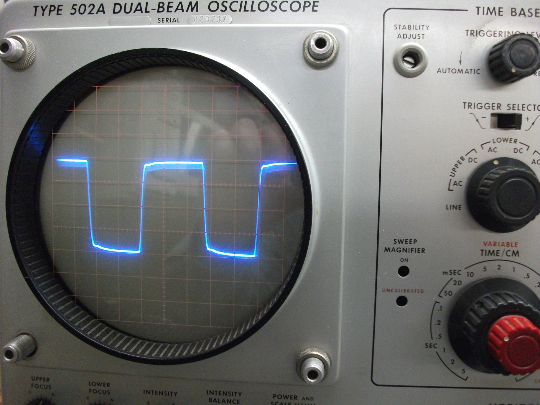
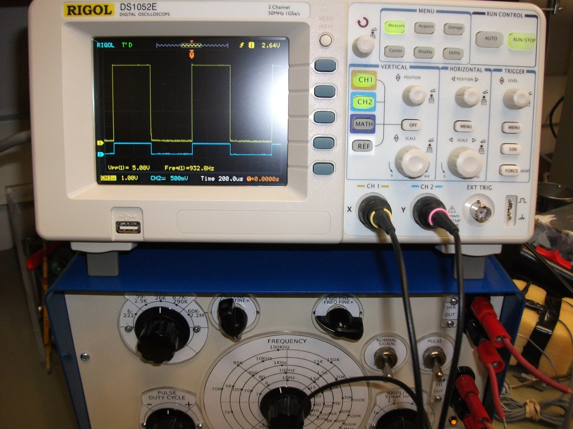
Low frequency operation.

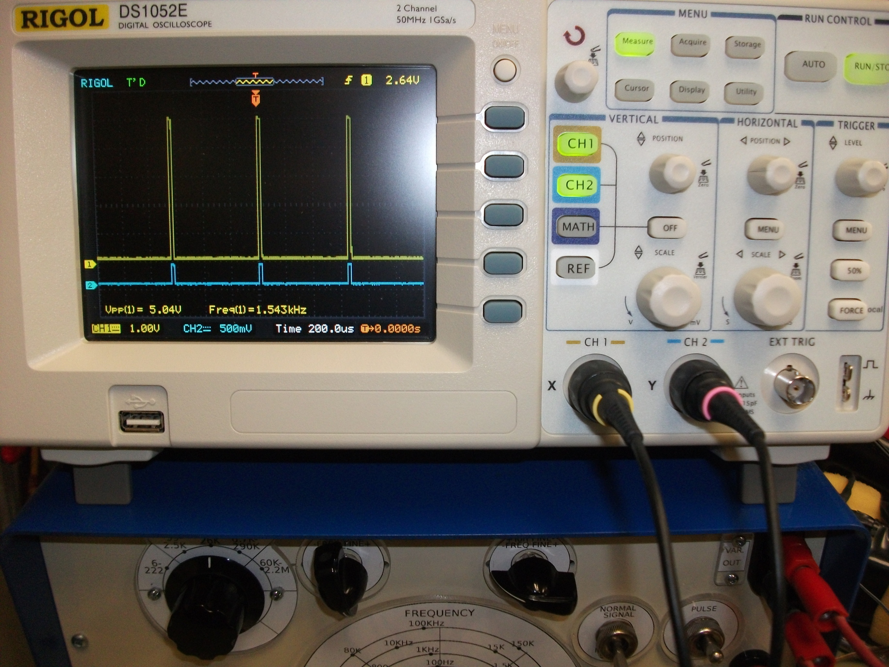
Demonstration of pulse generation. Pulse width can be varied
approximately from 1-49%, and with signal inversion (normal/invert
switch) from 51-99% (maximum, when frequency dial is in leftmost
position).
Other builds

Oliver from Berlin, Germany, built his own modified version.
Literature
1. GE Transistor Manual, 1964 edition.
2. Osnovi elektronike: Radio-predajnici i radio-prijemnici, Državni Sekretarijat za Narodnu Odbranu, 1967.
Translated into Serbocroatian from Soviet original (in Russian):
Основы радиотехники и радиолокации -
радиопередающие и радиоприемные устройства, Военное издательство министерства оборони СССР,
Москва 1965. В. Г. Левичев, Я. В. Степук, Б. И. Фогельсон. 1965.
Back to homepage