
Back to homepage
Regenerative radio receivers
This page covers several different regenerative receiver circuits that were used in the past,
mostly from 1920s to 1940s.
Connections are shown with vacuum tubes (vacuum valves), but FET transistors can often be
substituted with little changes.
Introduction
To those infected with radio bug, this page might be a useful resource.
It shows different connection setups for tube based regenerative receivers.
As such they might prove useful for new tube builds or FET/bipolar transistor implementations
and developments thereof.

Throughout, L1 is antenna coil, L2 main coil and L3 feedback "tickler" coil.
Headphones H can be replaced with audio transformer or suitable RC combination for connection
to next amplifier stage, in all circuits.

R1 is around 1 megaOhm, C2 around 100 picoFarads.
Triode connections
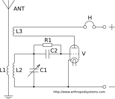
1. Classic connection - plain inductive reaction.
High frequency radio signal is coupled from antenna coil L1 to main tank circuit L2 - C1
used to select radio station.

Triode is connected as grid demodulator (audion).
Demodulated audio signal at anode is sent to headphones H.

Positive feedback is achieved with tickler coil L3, feeding back part of high frequency energy
from anode to grid circuit (coil L2).

Regulation of positive feedback is done by change of L2 <-> L3 distance, or by L3 rotation.


Coils L2 and L3 must have proper "polarity".
If they are wound in the same direction (say clockwise on coil form) they should be connected as
indicated on schematic.
If positive feedback cannot be achieved, try swapping L3 ends.
If it still doesn't work, L3 is too far away from L2, or it has insufficient number of turns.


For medium wave 540 - 1600 kHz reception, L1 should have about 5-10 turns, L2 around 80,
and L3 40-50 turns of insulated or lacquered copper wire on cylinder with 30 mm diameter.

If ferrite is used instead of air core coil, 10 mm cylinder diameter is sufficient.
C1 is 500 - 1000 pF maximum capacity variable capacitor.
R1 is 1 MegaOhm, C2 is 100 pF. Anode voltage is 40-80 volts.


Deficiency: it is somewhat difficult to make adjustable inductive coupling between L2 and L3.
Also, whenever L3 is moved closer or farther from L2, their mutual capacitance changes.
This means that main tank circuit L2 - C1 has to be sligtly adjusted again after every
change in regeneration level.
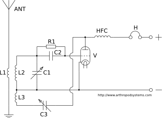
2. Inductive reaction with capacitive regulation
(Leithauser connection (in German parlance)).

Feedback regulation is now done with C3 (maximum capacity 250 - 500 pF).

Higher capacity means less impedance for HF current, and this means stronger reaction.
In this way it is possible to change feedback level in much finer way.

L2 and L3 are wound in the same direction, and on the same cylindrical form.
Their inductive coupling is now fixed.

HFC is high frequency choke (30 - 40 mH for MW (medium wave, AM)) which prevents flow of
HF currents into headphones.


Deficiency: sensitive to hand capacity, because C3 rotor is not grounded for HF currents.
If hand is moved closer to C3 for adjustment, its capacity slightly increases,
and this changes the reaction level.

Because of this, it is hard to adjust receiver for maximum sensitivity
(just before oscillations start).
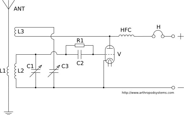
3. Inductive reaction with capacitive regulation of feedback.
Rotor of reaction capacitor is now grounded.

In this way hand capacity problem of schematic 2 is much reduced.
L2 and L3 cannot be wound in the same way (connected together) as in schematic 2, though.
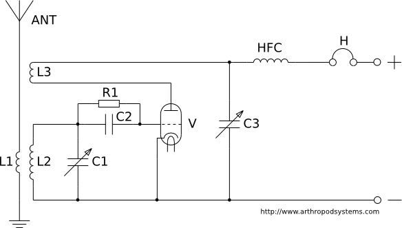
4. Schnell circuit.
Inductive reaction with capacitive feedback regulation
(adjustable C3, 200 - 300 pF maximum capacity).

This circuit has very small sensitivity to hand capacity, and fine reaction
regulation is possible.

Unfortunately, once C3 is adjusted, C1 has to be re-adjusted for maximum sensitivity.
This makes it harder to precisely calibrate frequency scale.
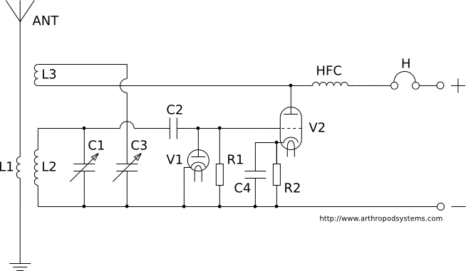
5. Nestel circuit.
This circuit has good tone quality and low audio distortion because demodulation is done in
a separate diode.

Vacuum triode V2 has negative grid bias, which allows very soft onset of oscillations,
and fine feedback regulation.
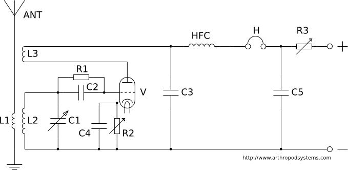
6. Reaction regulation with change in DC anode voltage.

Very stable and lacks hand capacity problems inherent in inductive feedback
with capacitive regulation.

R3 has 50 - 100 kiloOhms maximum resistance.
If maximum resistance is used, anode voltage is very low and oscillations stop.
If R3 is slowly reduced, oscillations will start.

With correct dimensioning of reaction coil L3 and reaction capacitor C3,
it is possible to achieve oscillation start in the middle of R3 resistance range.

Circuit is otherwise similar to Schnell (schematic 4 above).

C5 is added to aid in reduction of AC ripple, and to eliminate problems which may occur
from bad wiper contact in R3.

Supply voltage is around 100 V.
R2 is around 2 kiloOhms, C4 around 1 nanoFarad.

With R2 it is possible to adjust for optimal grid bias voltage of triode V.
With this we achieve good demodulation quality and high sensitivity.
Pentode connections
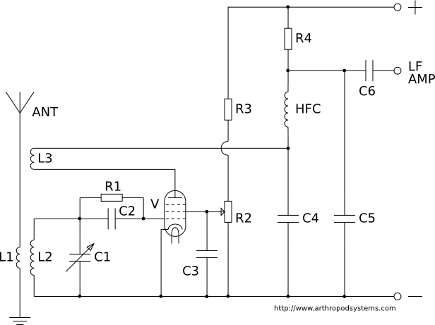
Pentode circuit.
Regulation of pentode gain is done with change in second grid voltage,
fully independent of frequency.

This changes anode current (current flowing through feedback coil L3).
Circuit performs even better than triode circuits.

R2 is around 50 kiloOhms, R3 around 100 kiloOhms.
Supply voltage is 200 - 250 V.
In this way voltage of second grid can be changed from 0 - 100 V.
Values should be adjusted for the particular pentode you are using.

C3 (100 nanoFarads) grounds second grid for HF.
Because of high internal impedance of pentode,
coupling to next stage cannot be done with transformer, so RC coupling is used.

R4 is around 200 kiloOhms, C6 is 10 nanoFarads.

C4 (200-300 pF) is reaction capacitor, C5 (100 pF) removes remnants of HF from audio output.
Literature
1. Radio-tehnika drugi dio, Zagreb, 1963.
Translated into Serbocroatian from German original:
Funktechnik Teil II, Dr. Walter Daudt, Berlin, 194?.
Back to homepage