... or how to use live or neutral wire in your home as receiving antenna
for long wave, medium wave, or short wave
Warning!
Warning: use of this antenna is not recommended if you do not use separate antenna coil,
high voltage capacitors and a fuse to connect to high voltage live wire.
You risk death otherwise.

Be careful and use all safety precautions.
Always assume that neutral wire might be live as well, if improperly wired.
Even if properly wired, it can become live due to a fault.
Live wire / neutral wire antenna
I was looking through some old radio books - mostly tube designs - when it was mentioned
that it's possible to use live or neutral wire in AC household wiring as a receiving antenna.

Of course, this is possible only with high voltage capacitor inserted between the receiver antenna
terminal and live or neutral wire.
AC wiring antenna solution was mentioned as some type of last resort,
when no other antenna can be installed due to space contraints.

Ground conductor can be used as Earth ground.

Old books recommend cold water pipe as ground connection, but I'm not sure whether this is
good/practical/allowed any more.
They also recommend "one good condenser" for antenna connection, not 2 in series.
I guess people were braver then :)
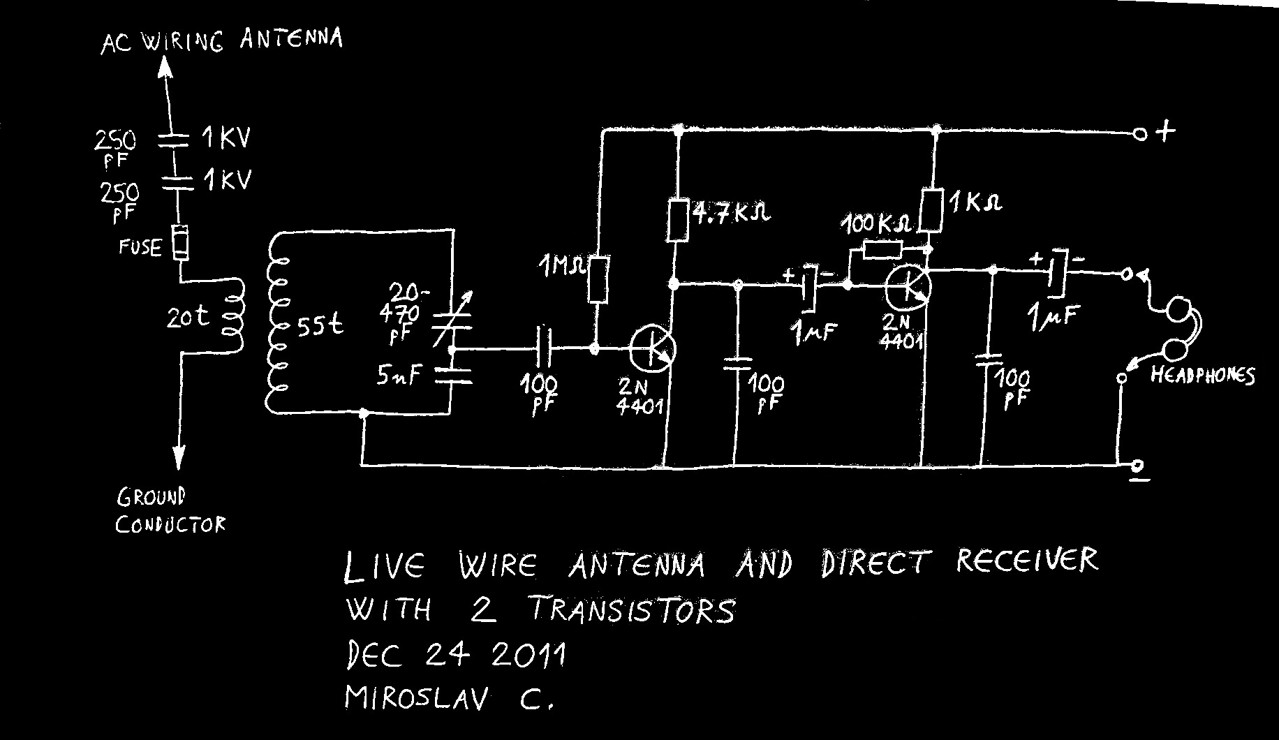
Receiver circuit and antenna connection
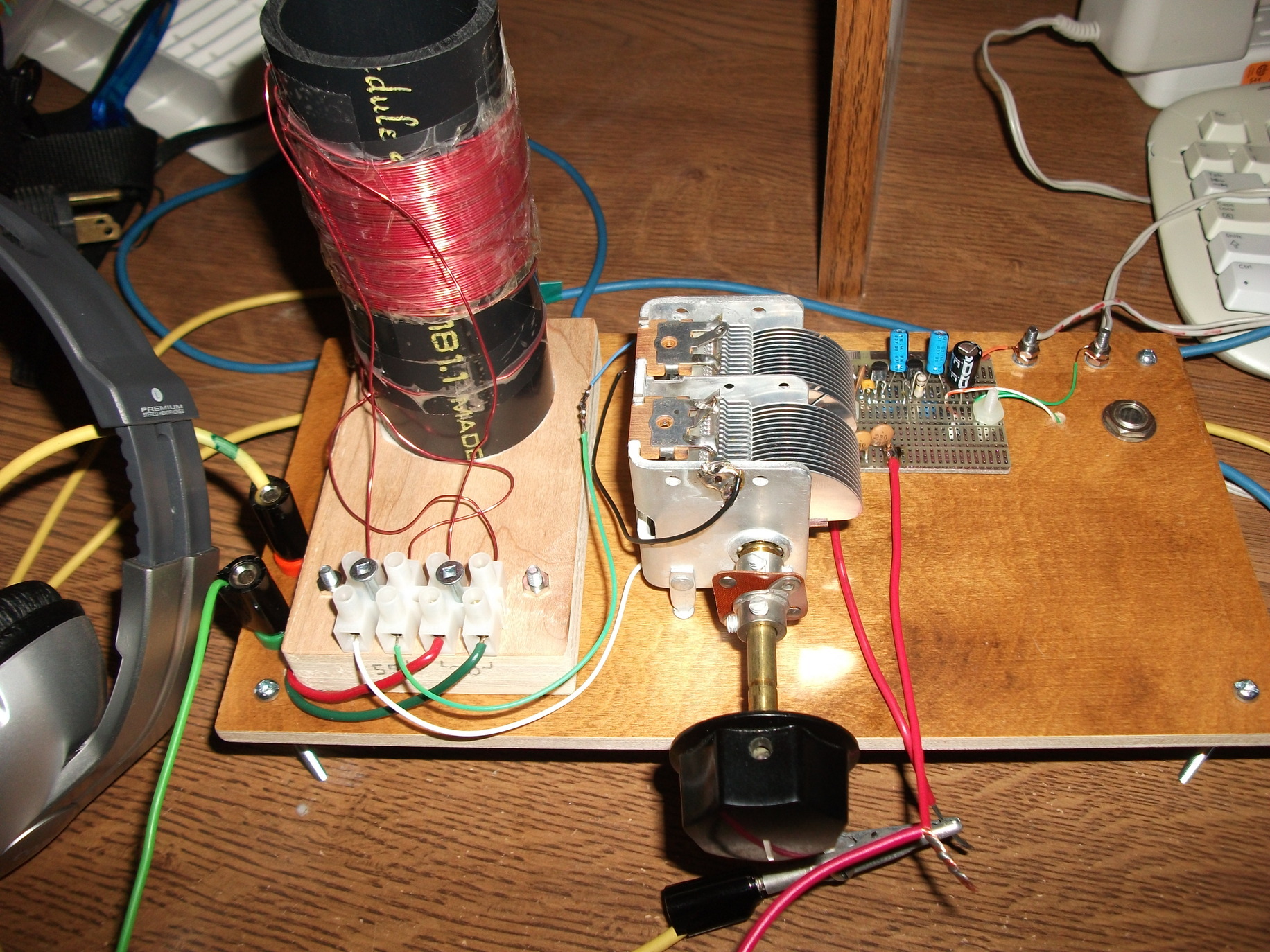
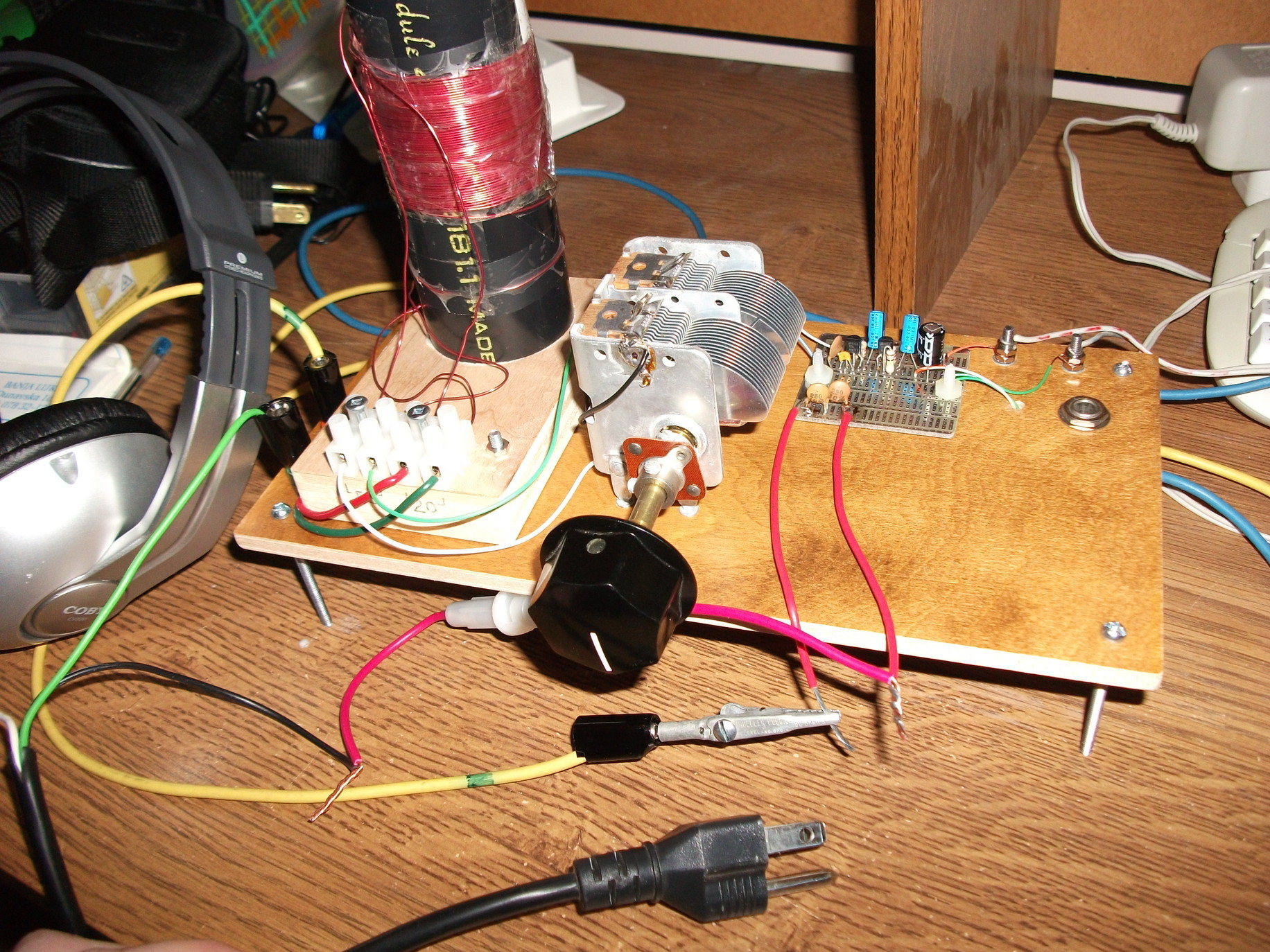
I decided to test this system myself.

I made a small 2-transistor medium-wave AM receiver, with headphone output.
To reduce main LC tank circuit loading, HF is taken from a capacitive divider of variable cap
and 5 nF cap.
Smaller voltage drop exists on larger capacitor due to its smaller capacitive reactance
Xc=1/(2*pi*f*C).

Voltage taken from main LC circuit decreases as higher frequencies are received: smaller
capacitance of variable cap takes on more of capacitive divider voltage.
This was deemed to be unimportant for fairly narrow range MW tuning.

Received high frequency is demodulated at the base of first transistor and then amplified
as low frequency in the first and second transistor.

Calculated frequency range is approximately 700 kHz - 2800 kHz.

To protect myself and my receiver, I decided to use two high voltage capacitors in series,
antenna coil galvanically separated from remainder of circuit, and fuse.

If high voltage spike is somehow able to penetrate through both 1 kV rated
capacitors, it will blow open the fuse.
Failing that, antenna coil (0.3 mm diameter wire, 20 turns) will burn out,
with no further damage done to receiver (or user).
Hopefully. :)
Simple MW AM direct receiver schematic with live wire antenna
connection shown.
Coil, variable capacitor and receiver circuit. Headphones can be of low
or
high impedance.
Testing
Several tests were done: first with 1 m wire antenna, without ground connection.
Four nearby AM stations were received, 3 were identified for testing.

Latter tests were done with live wire antenna connected to AC outlet,
neutral wire antenna connected to AC outlet, and lastly power cable antenna
NOT plugged into the outlet.
Connection setup with live wire (black wire) connected as antenna.
Male power plug not plugged into the outlet.
Testing video with live wire as antenna.
Antenna is plugged into the AC outlet during the video.
This changes main receiver LC circuit frequency somewhat, so re-tunning is necessary
for maximum sound output. Sound is weak because it is coming from the headphones only,
so weaker stations cannot be heard in the video.
1.
1 m wire antenna, no Earth connection, Dec 24, 2:30 PM
Station frequency (kHz)
Transmitter power (kW)
Vrms (at headphones)
Reception
Distance to TX (km)
CHML 900
50
10 mV
strong
20
CKOC 1150
50
55 mV
very strong
15
CKPC 1380
25
2.7 mV
weak
30?
Clear but fairly weak signals.
2.
live wire antenna, Earth connection to grounded cable conductor, cable
plugged into AC outlet, Dec 24, 3 PM
Station frequency (kHz)
Transmitter power (kW)
Vrms (at headphones)
Reception
Distance to TX (km)
CHML 900
50
40 mV
strong+noisy
20
CKOC 1150
50
115 mV
very strong
15
CKPC 1380
25
45 mV
strong+noisy
30?
Noticeable 60 Hz hum. Measured at headphones: 2.3 mV at 700 kHz, 0 mV
at 2800 kHz.
3.
neutral wire antenna, Earth connection to grounded cable conductor,
cable plugged into AC outlet, Dec 24, 3:30 PM
Station frequency (kHz)
Transmitter power (kW)
Vrms (at headphones)
Reception
Distance to TX (km)
CHML 900
50
100 mV
strong
20
CKOC 1150
50
125 mV
very strong
15
CKPC 1380
25
80 mV
medium+noisy
30?
Some 60 Hz hum.
4.
live wire antenna, Earth connection to grounded cable conductor, cable
NOT plugged into AC outlet, Dec 24, 4 PM
Station frequency (kHz)
Transmitter power (kW)
Vrms (at headphones)
Reception
Distance to TX (km)
CHML 900
50
90 mV
strong
20
CKOC 1150
50
120 mV
very strong
15
CKPC 1380
25
8 mV
weak
30?
Clear signals.
Fourth station received and understandable, but not used for testing, was 820 kHz CHAM,
15 km distance to TX, 30 mV at headphones, 50 kW TX.

Measured with live wire antenna, Earth connection to grounded cable conductor, cable
NOT plugged into AC outlet.
Discussion
Regular 6 feet (1.8 m) power cable, even when not plugged into the outlet,
provides surprisingly good reception, much better than just single 1 m wire.
I suspect this has something to do with the fact that antenna and ground wire are
identical in length, which makes it into a crude non-resonant dipole antenna
(but with parallel arms instead of 180 degree arms). Or not.

Live wire / neutral wire antenna connections provide a lot of usable signal,
so my judgment is that this is a viable way to have some antenna if nothing else is available.
Main problem: 60 Hz hum that masks weak stations.

It could be reduced in two ways:

1.
Use smaller number of turns for antenna coil. 20 is way too much, 5 will do just fine.
It will provide better impedance match to main tuning circuit, and reduce inductive reactance
(less 60 Hz voltage induced into antenna).

At 1 Mhz inductive reactance of 20 turns antenna coil with inductance of 40 microH:
XL = 2*pi*f*L = 6.28*1000000*0.00004 = 251 Ohms

At 60 Hz inductive reactance is:
XL = 6.28*60*0.00004 = 0.015 Ohms

Voltage drop on antenna coil is sum of voltage drops on XL and antenna coil resistance.
Resistance is approximately 0.4 Ohms.

2.
Use smaller antenna capacitors. Test setup used two 250 pF 1 kV capacitors in series.
This gave total capacitance of 125 pF.
Capacitors in 10-50 pF range should be sufficient.
They will weaken 60 Hz hum as well being of higher capacitive reactance at 60 Hz
(smaller cap - higher capacitive reactance).

At 1 Mhz capacitive reactance of 125 pf antenna capacitors:
Xc=1/2*pi*f*C = 1/(6.28*1000000*0.000000000125) = 1273 Ohms

At 60 Hz capacitive reactance is:
Xc=1/(6.28*60*0.000000000125) = 21.23 MegaOhms
How much voltage is 60 Hz power line voltage inducing into the antenna coil?
At 60 Hz we have, in essence, series R, L, C connection.
Impedance of L being very small, we have to practically deal only with series
connection of impedance Xc and coil resistance Rcoil.
Voltage induced is then:

Vinduced = Vac * (Rcoil / Xc) = 120 V * (0.4 / 21 230 000) = 2.26 microVolts
which agrees well with measured values (see table 2, live wire antenna).
Okay, but how do I use this in my own radio?
Most people will not be building their own receivers to test this.
Here are a couple of suggestions:

1.
If you just have one connector labeled antenna, ANT or similar, you can try to connect to
neutral/live wire with two high voltage capacitors and fuse in between your connector and
neutral/live wire.

2.
If you have two connectors, labeled antenna, ANT and Earth, -||| or similar,
connect to neutral/live wire with two high voltage capacitors and fuse in between your
ANT connector and neutral/live wire.

Connect Earth connector to grounded conductor in your power (turned into antenna) cable.

3.
Cheap transistor radio with no external antenna connections?
You can open the radio, and wind one turn of insulated wire onto radio's ferrite rod antenna.
One end of wire goes to 2 high voltage caps + fuse and then to live/neutral wire.
Other end goes to grounded conductor.
Conclusion
Neutral wire antenna was overall the best, so for safety reasons it would be wise to use
neutral conductor as antenna.
Your local conditions may vary however, in which case you may find that live wire
antenna is better.