Idea when building this machine was to see how inexpensive the machine can be, and still perform acceptably.
"Acceptable" means slow and light duty wood carving. Some plastic also.
I was thinking about the machine on and off for quite a long time.
However, only when I started acquiring parts real construction process began.
Sometimes I didn't even know what will be my next step, because parts were obtained "on-the-go".
I do not recommend such building practices ... but I don't recommend spending 1000 hours sitting
on a chair designing in CAD either.

Biggest obstacles were mechanical.
Specifically, linear sliding mechanism and shaft coupling needed to be solved.
My task was made harder by absence of proper metal-working tools.
In the end, all problems were solved. Below is the construction
process with pictures.
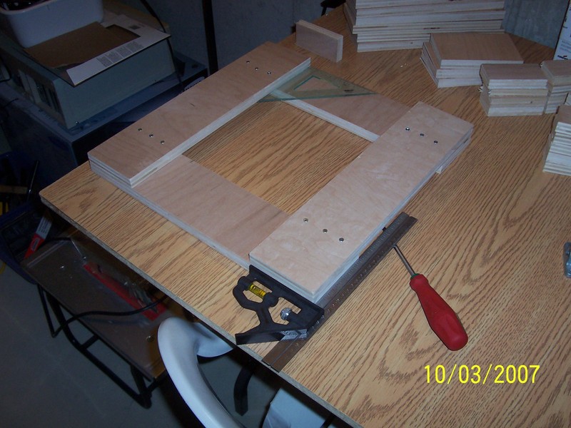
Initially, I cut four identical pieces of plywood 430x100 mm.
They were screwed together with wood screws into square like structure.
There's really no need to do this. You can simply use square board.
I did it because I couldn't precisely cut those pieces at home,
and precision was deemed to be important for base. It isn't.
I couldn't get this to work. Binding problems caused me to abandon this approach for linear slides after
one futile day spent.

Even after filing the pillow blocks and sanding bumps on shafts, it kept sticking badly.
I guess if I continued with that it would work, but with my hand tools it would take a while.

Required precision in my amateur work just wasn't there. And I've become impatient :) and switched to plan B.
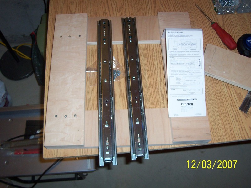
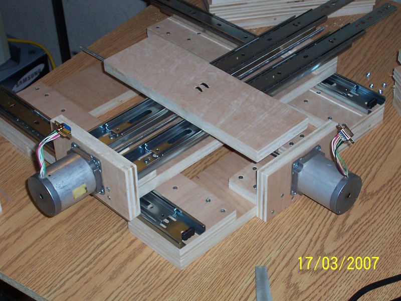
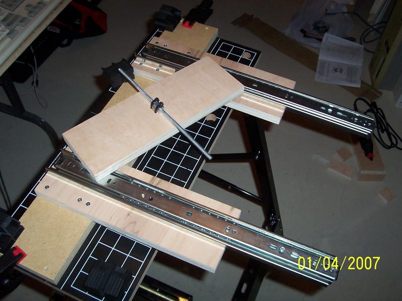
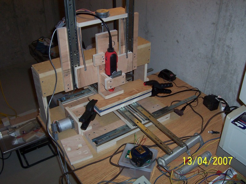
After this I went to Home Depot and bought high-quality ball-bearing drawer slides ($18 for pair).
I installed them the very next day and they worked beautifully.
Total of 3 slide pairs ended up being used (for X,Y,Z, 3x$18).
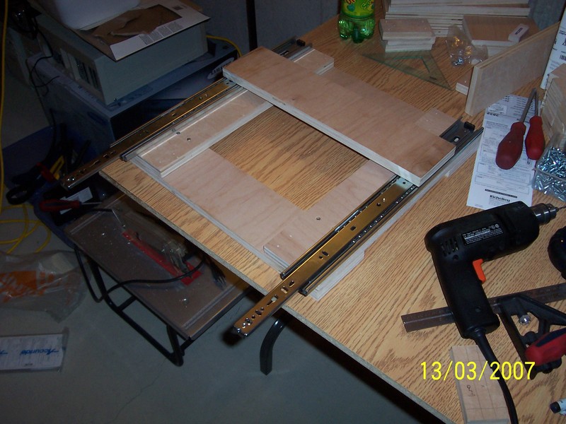
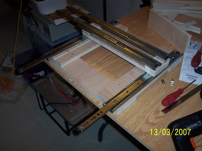
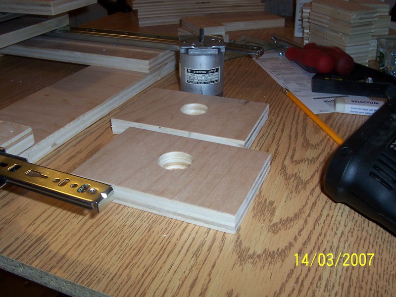
I was then able to test X and Y operation by hand. I was thrilled and jubilant.
Essentially, my linear sliding problem was solved.

Next, I wanted to see whether I can solve my next biggest problem:
Attachment of stepper motor shafts to 6.35 mm (0.25 in.) threaded rod.

For this I planned to use 6.35 mm shrink wrap or cable insulation stripped off,
then secure it on shaft with plastic cable ties, insert threaded rod into other end of
shrink-wrap or stripped insulation cylinder, and secure with more plastic cable ties.
This worked very well, and almost never gave-up in all my trials so far.

To start I drilled big holes for stepper motor shafts in my previously cut motor support
plywood plates 150x100 mm.
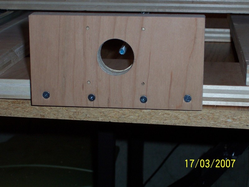
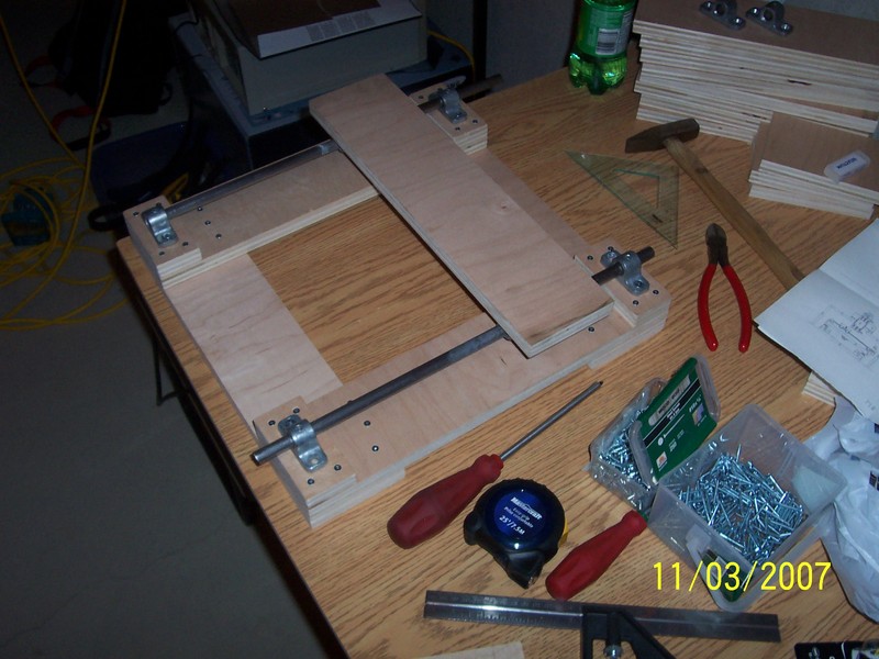
Coupling nuts were secured to X and Y boards. 4 holes were drilled in each board around a nut.
Nut is then secured by 2 plastic tie-wraps.

Once that was done attempts were made to run X an Y by hand.
However, nuts eventually slipped out after few days.
Then I decided to epoxy them in place. After this I never had any problems with them.
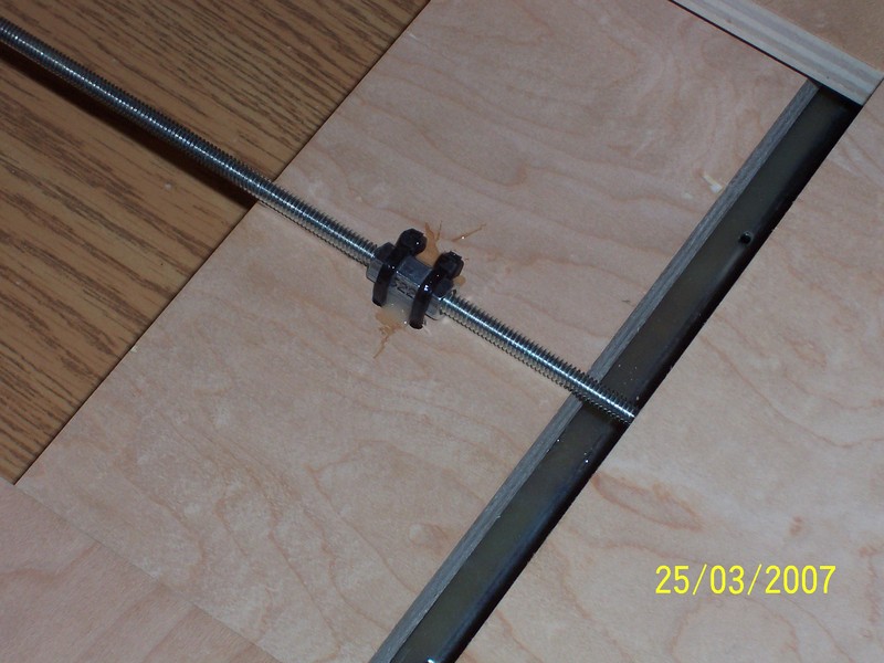
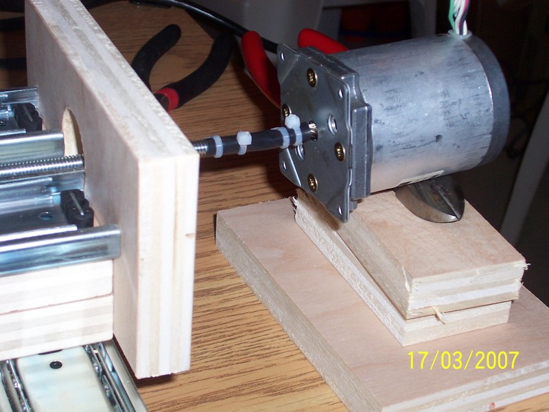
After X and Y movable boards were equipped with nuts and nuts were glued,
threaded rods were inserted into the nuts.
Then, stepper motors shafts were secured to threaded rods using shrink-wrap and
plastic cable ties.
This being done, steppers were attached to motor plates with wood screws.

Proper position of the motor shaft is the center of imaginary circle that threaded rod
end (inserted into nut) makes when moved by hand in circles.
This position gives least friction and eliminates binding.
This was found by trial and error (see below).
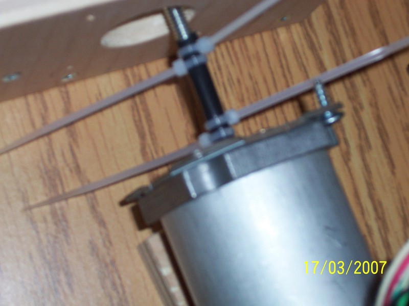
I was able to turn the shafts by hand. But one axis was binding a bit.
Solution: repositioning of motor about 4 mm lower.
Threaded rod turned very easily when turned by hand after that.
After several days, cables, electronics, and control software were brought
up from non-existence into barely workable state.
Then, first motor trials for X,Y took place.
After three days of frustration, three wiring errors to motors were corrected :)
Once X and Y were working, I decided to quickly cobble-up Z-axis-like stand so I can test
2D pencil drawing by machine.
This was done faster than Soviet Union's factories could produce a tank in WW2.
And I had first drawings made by machine and pencil.
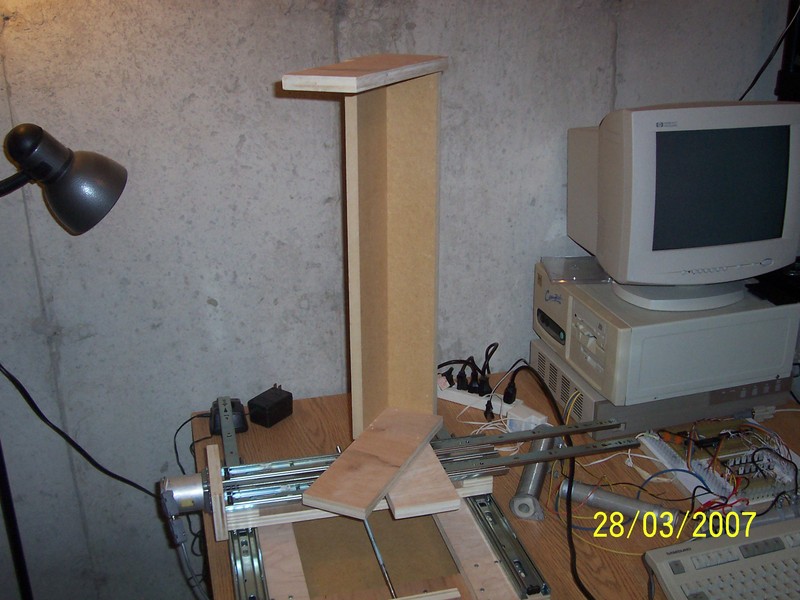
First drawing. A historic moment.
"This is one small step for pencil, but great leap for mankind" :)
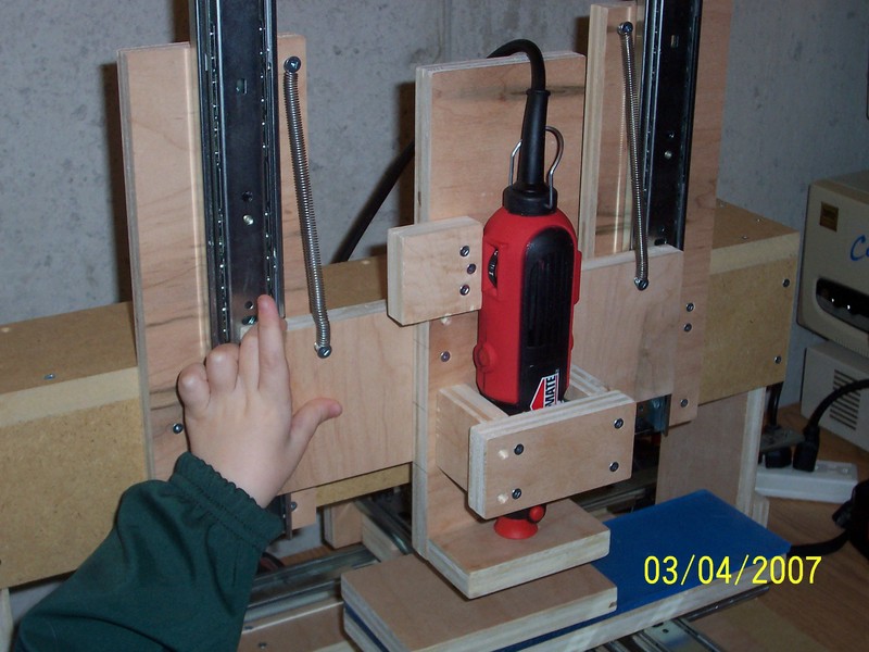
Once I had played a bit with pencil, all the while improving the hardware and software,
I decided it was time to move to a "proper" Z-axis.
To do this, in parallel I had to make a rotary tool holder.
Being impatient, I quickly put the holder together using some spare wood pieces I cut
wisely at the beginning of construction.
They were actually planned to make corners stronger :)
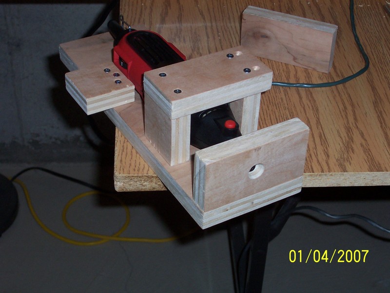
Once the holder was done, it was screwed onto Z-axis slider board, much
like the ones already proven on X,Y axes.

Z axis slider:
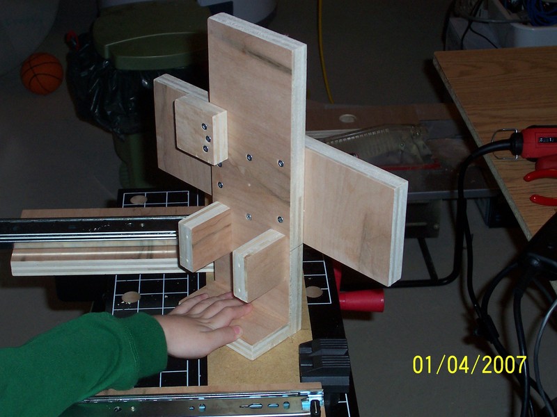
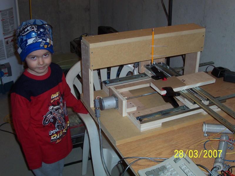
Motor
was attached to threaded rod in much the same way as X,Y.

But it didn't work this time, because weight of Z-axis pulled the shrink wrap and cable ties
right off the stepper shaft.
Plus shaft wasn't 6.35 mm diameter as XY stepper shafts were, but around 3 mm.

To counter weight issue, I used 2 springs connected from movable Z table to the fixed Z axis structure.
This offloaded almost all the weight from movable Z platform.
Some people use counterweights, and I think that is even better solution (but not simpler).

Spring olution works well for small range (3-5 cm) of Z movement.
More than that and motor is struggling to keep up. Main engineer's (Marko's) hand visible.
To counter dissimilar shaft and rod diameters, I've used small piece of rubber wrapped around
the 3 mm stepper shaft.
Then, shrink wrap was put on it and bundle tied with plastic cable ties.
The other end of shrink wrap cylinder was connected in usual way (see above X,Y) to threaded rod.
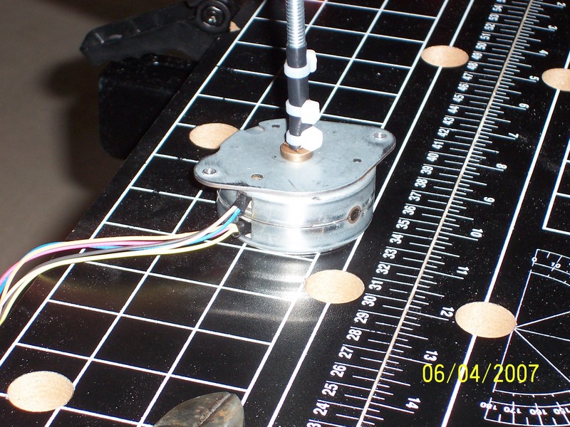
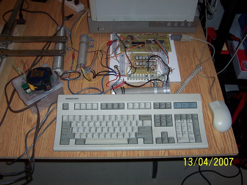
Rubber used was intended for kitchen drawer rubber mat.
It is 1mm thick and comes in colourful rolls at your local Dollar store.
Those two solutions worked almost perfectly so far.

Control board (serial port + PIC micro + TIP122 transistors + motor coils).
Also controls relay that turns rotary tool on-off (used for periodic cooling and noise remedy).
Relay is in the box underneath the measuring tape :)
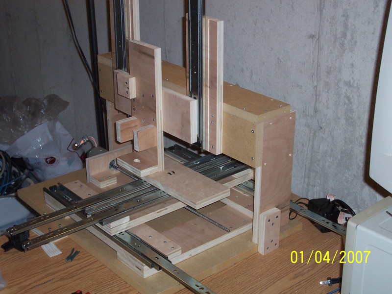
Then came the time to test the whole thing, especially Z-axis setup.
All came out pretty good, design is pretty sturdy.
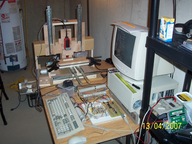
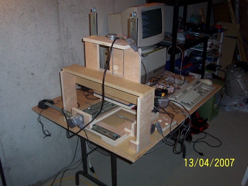
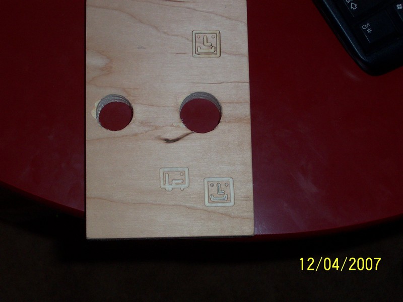
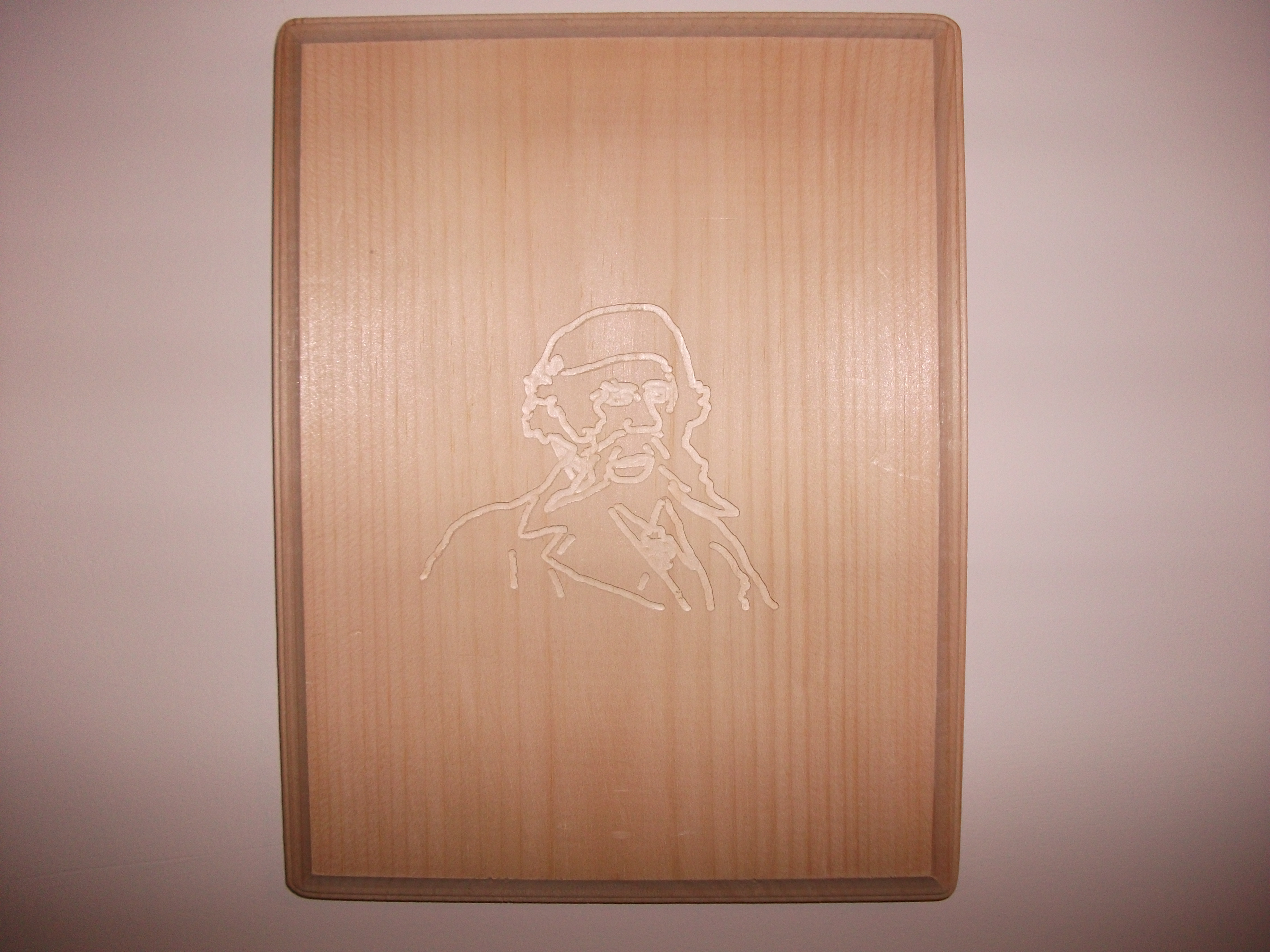
Image showing first carvings (robot faces in lower right corner).
Each took 12 minutes to complete.
With progress being made, it can be done in much shorter time now.

Top carving was made few days latter in 6 minutes and with higher rotary tool speed
(straight lines now but little burned up compared to original).
Done with around 2 mm diameter ball-nosed dental drill bit :) to a depth of 1 mm.
Carving based on 19th century drawing of a historic figure.
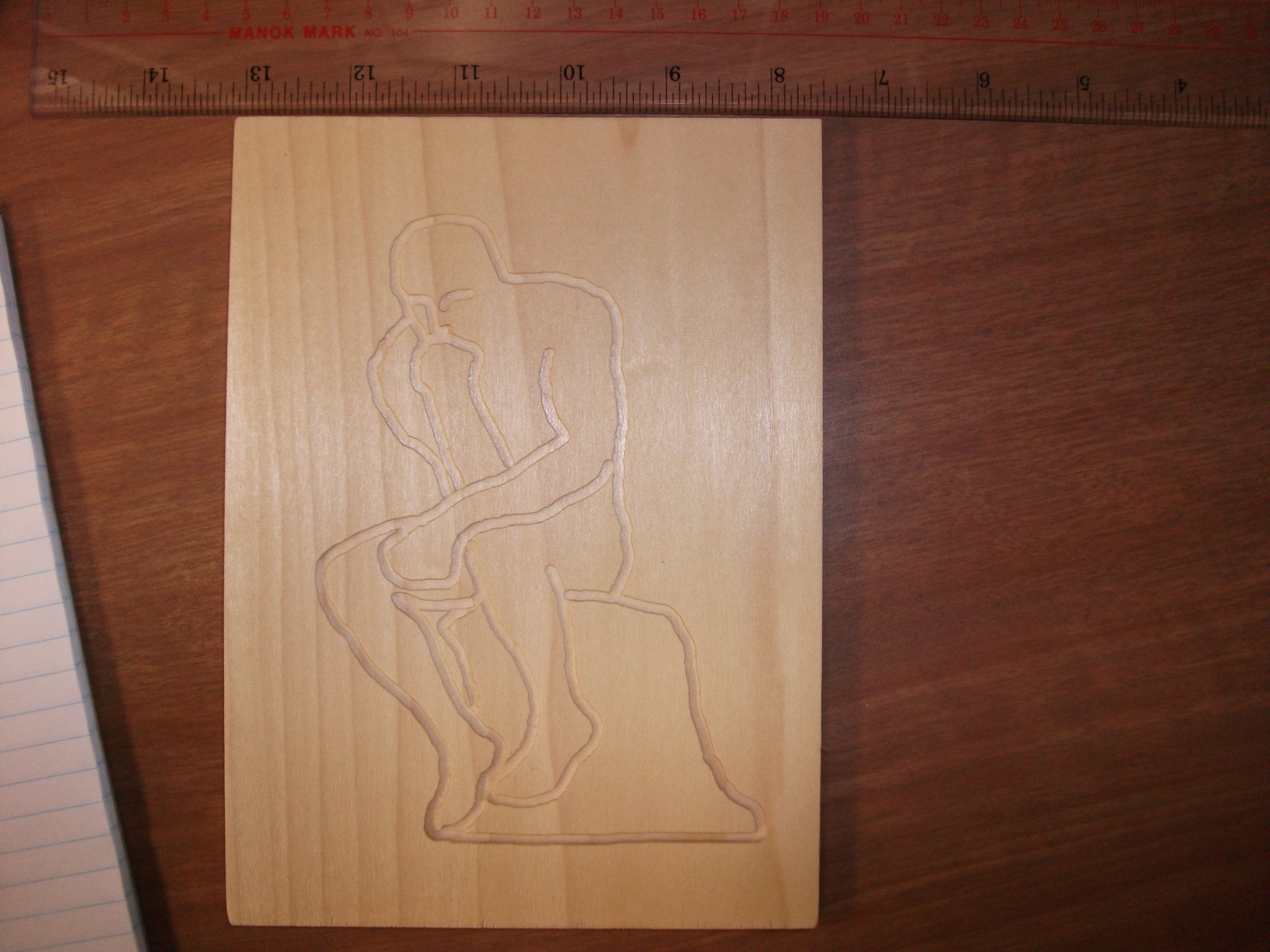
Another carving based on well known sculpture.
Video of machine in operation.
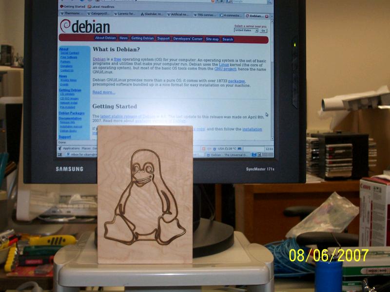
Many thanks go to Debian GNU/Linux community, which made everything
possible, and other people in FOSS community.
3-axis X,Y,Z. X and Y move object to be machined left, right, back and forward.
Z support doesn't move and is attached to the base.
Z platform is attached to Z support and moves rotary tool up-down.

Each axis equipped with 20 tpi (threads-per-inch) 0.25 inch diameter threaded rod for rotary to
linear motion conversion.
Also, I'm using elongated 0.25 inch I.D. nuts attached to movable tables.

It appears that their proper name is "coupling nuts" :).

X and Y axis: 200 steps per revolution, 1.8 deg./step, 5.2 V, 3.3 Ohms/coil, unipolar steppers.
Z axis: 48 steps per revolution, 7.5 deg./step, ? V, 9 Ohms/coil, unipolar stepper.

Using drawer slides for linear sliding (:-)) movement.
Currently done through serial port, using custom Python program. Python program uses pyserial, pygame and Numeric libraries, which must be installed before program can be used. Program is command line only. It is available for download (link bellow) under GNU GPL. It can operate in manual mode or read and engrave grayscale or black and white pictures. Darker regions in image will be cut, whiter ones not. Python program communicates with Microchip PIC16F874A microcontroller. PIC then turns on and off 12 TIP122 Darlington transistors connected to 3 Motors x 4 CoilsPerMotor = 12 coils.PIC program
Control software can be used in Debian GNU/Linux or Windows 2000. Other Windows or Linux versions not tested. Windows communication timing is currently problematical though, so speeds are much lower in Win. To clarify this, time between serial "data packets" is minimum 7 ms in Windows 2000. In Debian GNU/Linux, current speed is as low as 0.63 ms.Download necessary Python program for PC and asm program for PIC microcontrollerSchematics
First version shown. Minor errors possible.
Speed of operation
Software currently supports speed of up to 158 steps/second (with stable software). This was accomplished by increasing the operating voltage from 5 V to 12V, then to 24V. Read below for origin of this voltage increase. At 125 steps/second speed, current pulse duration for resistive load is 4.7 ms, motors X and Y are barely keeping up, and Z clearly loses many steps. All this using 5V. Those effects did not show at lower speeds (0-50 steps /second). To counter this, literature recommends increasing supply voltage and connecting external resistor. In this way, L/R constant is reduced, and coil inductance effects are proportionally diminished. This was done using 12 V supply and external resistors (one for X,Y, one for Z) because motors have different current ratings. It significantly improved response and now everything is OK at 125 steps/second. To improve speed still further, I have made 20-24 V supply now, which permits 158 steps/second. Reason for this speed requirement is that X and Y motors need to make 200 steps to rotate the threaded rod 1 revolution, which gives linear movement of 1.27 mm (1/20 inches). For reasonable machining and positioning times, speed must be increased. Speed for Z axis is acceptable to me, because (125 steps/sec) / (48 steps/rev.) = 2.6 rev./sec., which gives 2.6*1.27mm=maximum 3.3mm/second movement for Z axis. X and Y are only around 0.75mm/sec. maximum (at 125 steps/s), which is too slow for positioning, but acceptable for machining.
Rotary tool heating problems
I mention this because I use $15 rotary tool, whose power is limited. It also overheats quickly. To counter this, relay turns the rotary tool off and the program execution is stopped for several minutes every 10-minutes or so. This permits natural cooling of the rotary tool to take place. Speed settings on rotary tool are 1,2,3,4,5 and MAX. Rotary tool heats up much less when carving at higher speed (5). Internal fan works better, and also it is not struggling to cut the wood anymore. Before it was merely "ripping" the wood, now it carves :)))
Bill Of Materials
Drawer slides, 18 in. - 3x $18 Screws #6, box - 1x $8 Screws #10, box - 1x $8 Plywood, Maple, 19 mm (0.75 in.) thick - 1x $20 MDF board, 19 mm (0.75 in.) thick - 1x $12 Threaded rod, 6.35 mm (0.25 in.) O.D. - 3x$3 Coupling nuts, 6.35 mm (0.25 in.) I.D. - 3x $2 Rotary tool, Jobmate - 1x $15 Total: $132 Canadian. Things obtained for free: stepper motors (3 old printers), cables (old reused cables), electronic parts (had them from before), 5V and 12V power supply (postal office junk), bits for engraving (dental drill bits, Dr. Daniel B.), PC (McMaster University, discarded Pentium 1 at 233 MHz), Operating System (Debian GNU/Linux), Control Software (Python, Me, Myself and I) Elbow grease (Marko and I) Other stuff.
Final thoughts
I'm writing this part in 2011, after several years of on/off (mostly off :)) machine use. I do plan to eventually make another machine, and here I will summarize major problems that should be rectified in the next one. Speed. It was found that speed for X Y motors is insufficient. Many expedients were tried, but speed problem was only partially resolved. First part of the problem stems from the fact that X Y steppers have 200 steps per revolution. Second part is acceleration/deceleration routine, which was never built in into the PIC, due to the fact that long stretches of straight carving were never needed. Third problem is control type – sending individual steps via serial port proved to be too slow and somewhat dumb :) Noise. Noise levels when rotary tool is working are unbearable. I have used ear protectors and latter I have made a cardboard box with holes to put onto the machine while it is working, to reduce noise. Reduction in rotary tool speed reduces its ability to carve, so that method for noise reduction was dropped. Dust. Dust problem is unresolved. It appears that the best bet would be to connect a vacuum cleaner hose close to the tool tip. To prevent even more unbearable noise (rotary tool + vacuum cleaner) it would be wise to adopt lower power vacuum or battery model. Cutting power. Rotary tool that I have used is great for softwood, but barely enough to keep up with hardwood even at low speed of 1.2 mm/second.
Useful web sites
http://www.cnczone.com - if you want to get serious
http://www.debian.org - really good operating system and philosophy, with simplest update system among many Linux distributions (not counting those derived from it)