Back to homepage
Analog computer 1
Introduction
Analog computer is a type of computer that works with continuously changing variables,
as opposed to digital computer that uses discrete values.
Digital computers are almost always electronic or electromechanical devices,
while analog types can use any continous
variable: voltage, water flow,
air pressure, length (slide rule) and other.
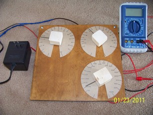
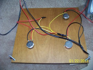
Finished analog computer.
While first modern computers were analog electromechanical differential analyzers in the 1930s,
soon thereafter they were faced with competition from electronic digital computers.
By 1960s, pace of miniaturization of digital components meant that digital computers became less
expensive than analog ones, while being able to produce exact answers, a must for many human endeavors.

Analog computers continued in use for simulation of complex physical processes, but even here they were
eventually superseded by simulations run on digital computers.

Having said that, they were (and still are) excellent tools for simulation of real world.
One gets much better understanding of certain phenomena by being able to directly change the variables
and see the outcome immediately.
Article
Sometime ago I stumbled upon an article
about very simple analog computer in a 1961 scanned Popular Electronics magazine.
This pushed me to make a copy along similar lines.

Only components needed are three potentiometers, battery/or AC/DC adapter/or step-down transformer,
and voltmeter/galvanometer/headphones.

Digital voltmeter will do just fine, and most people have that.
Analog meter is fine, but it is rarely seen nowadays.

My pots one and three (R1, R3) have value of 250 Ohms, and second one (R2) 25 kiloOhms.
Potentiometer values are not critical, BUT second potentiometer R2 must be much
larger in value than the first one, to reduce voltage divider R1 loading.
With value 100x greater, loading error is approximately 1%.
With R2 only 10x greater than R1, loading error is around 10%.

Supply voltage is not critical, it can be anything from 1 to 10 volts, DC or AC.

If you use headphones instead of a voltmeter to detect nulls, you must use some AC voltage source
instead of DC (for example 120 Vac/6 Vac transformer).
In that case, headphone buzzing will disappear once your solution pot R3 is set to proper solution.
If you use DC with headphones you won't hear anything anywhere on the scale - computer
won't work. Sound requires variable (AC) voltage.
Schematic
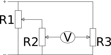
I made a schematic based on the original article. R1 is pot used for setting the first variable,
R2 is used for second variable, and R3 is the "result" potentiometer.

If R1 pot is set to 0.5 (50%) of its maximum value, this means that one half of the supply voltage shows
between R1 pot wiper and ground.
If R2 is now set to 0.2 (20%) of its maximum value, its output (wiper-ground voltage) will show only
0.5*0.2=0.1 (10%) of supply voltage.

We have effectively created a voltage multiplier.

When wiper of R3 is set to the same setting (10% maximum resistance from ground to wiper),
voltages at wipers of pots R2 and R3 will be the same, and voltmeter will read zero.
Voltmeter will read a nonzero value (error voltage) for any other setting of R3.
In this manner, R3 can be used, when calibrated, to show multiplied (already scaled) voltage value at wiper of R2.
Build
A quarter inch thick wooden tile was drilled for three potentiometer shafts.
After inserting the pots and securing them, knobs were put in place and plastic tie-wraps were put around the
knobs to serve as scale pointers.

I had some issues with knobs that I have selected, so I decided to replace them with wooden blocks (from 2x4s)
into which I have put some small nails for pointers.
They were drilled with holes somewhat smaller than pot shafts, so they fit snugly when forced onto them.
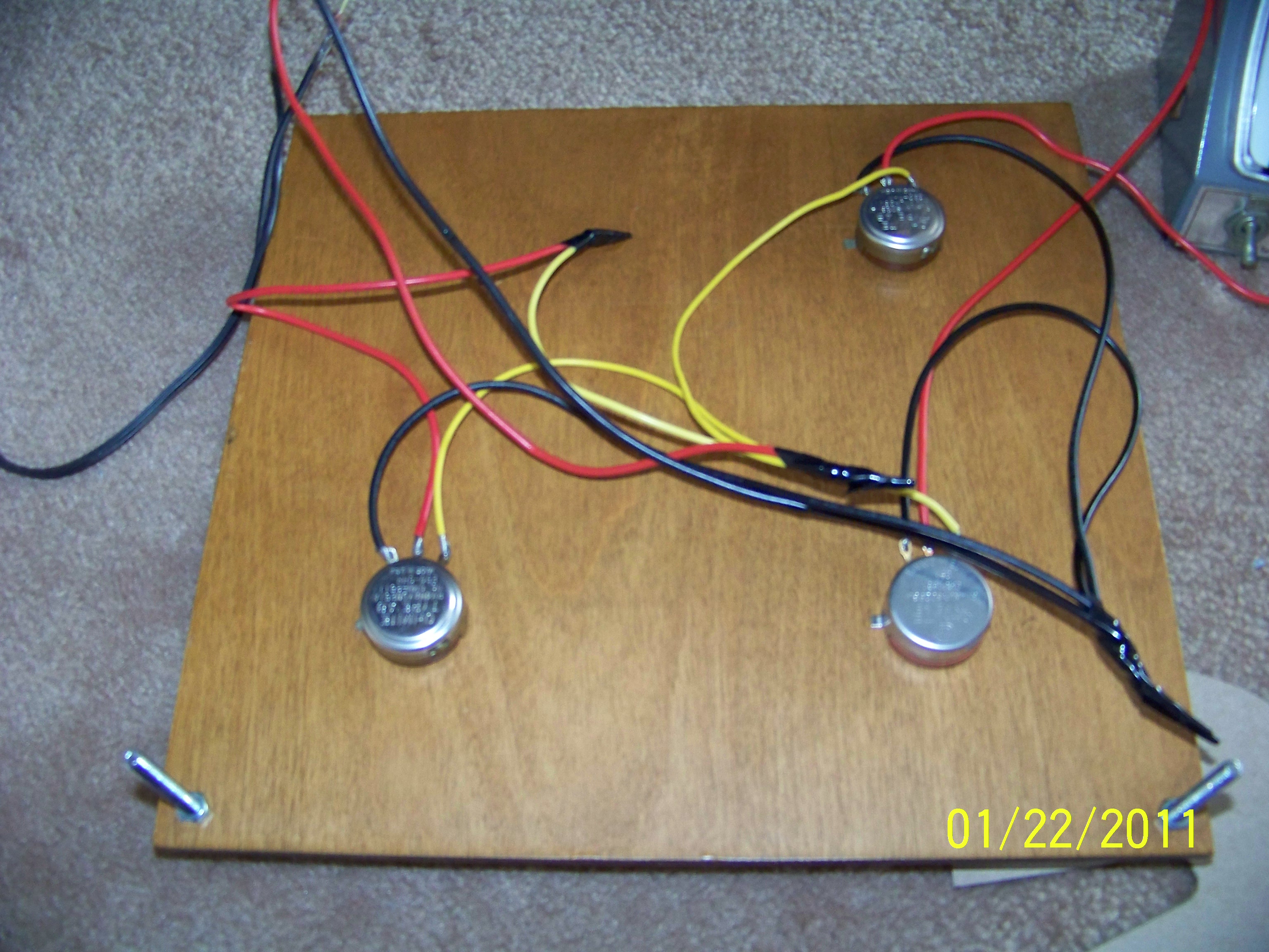
Board backside.
Round scales were traced out on cereal box cardboard and cut out.
They were glued to the wooden faceplate.

Next, without making connections between the pots themselves, you need to calibrate the scales.
To do this, first mark minimum and maximum pot positions (for regular pots around 300 degrees are swept).
Measure total maximum pot resistance (let's say 250 Ohms).
Connect your ohmeter between grounded pot terminal (pick one side tab) and pot wiper (central tab),
and slowly increase resistance until you reach 1/10th of maximum pot resistance (in my case 25 Ohms).
Mark this point with longer line and label 10.

Next move to 2/10ths of max. resistance position and mark this point with next long line and label 20.
Proceed until all tenths are marked.
If you wish, you can also mark 5/100, 15/100, 25/100 spots, you will obtain better precision.

Same process was repeated for other two pots, except that labels for third pot had increments of 1000
and maximum value of 10000.
After finishing calibration, connections were made according to article schematics.
Alternative method of calibration for third pot (that in hindsight appears to be somewhat more precise)
is to set two multipliers R1 and R2, calculate their product on calculator, and mark that result on third scale.

It does feel like a bit of cheating though :)
Fine... But what does it do?
Multiplication, division, squaring of numbers, and finds the square root of given number.
Maximum result is 10000, and variables 1 and 2 have a maximum value of 100.

Suitable scaling can be used, so if you add three zeros to variables 1, 2 and result,
maximum result is now 10 000 000 000.
If variables 1 and 2 are numbers very different in size, precision will suffer.
Average precision in optimal middle-to-high R3 scale range is 2-3%,
but falls off rapidly towards the low end of the scale.
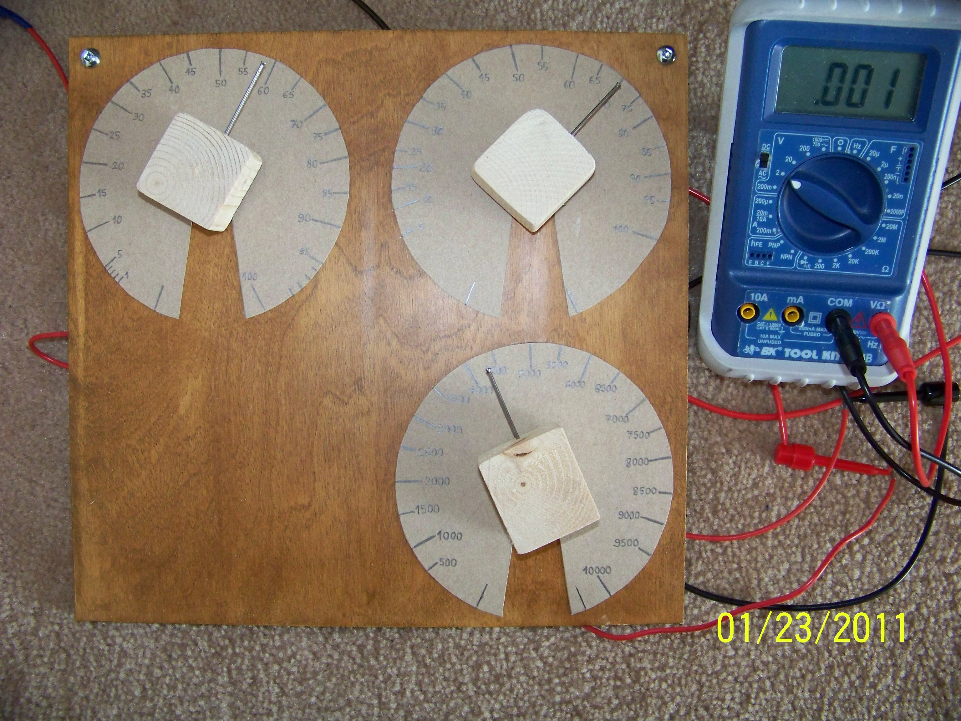
Multiplication
Just set dials 1 and 2 to desired values for multiplication, for example 70 and 80.

Now turn dial 3 (result) until you can read exactly 0 volts on your voltmeter.
Read multiplied result from scale three.

Multiplication/Division.
Division
Set number to be divided on scale 3. Set number to divide with on scale 2.
Turn dial of scale 1 until voltmeter reads zero. Then read result
from scale 1.
Squaring
Set number to be squared on dial 1. Set that same number on scale 2.
Turn dial 3 until voltmeter reads zero. Read result from scale 3.
Square root
Set number for which the square root is to be found on scale three. Now
turn dials 1 and 2 until both are set on the same numbers, and
voltmeter reads zero (this takes some practice). Number on scale 1 (or
2) is the square root of the number shown on scale 3.
Useful links
An
introduction to analog computer - in Popular Electronics magazine, 1961
Analog computer
- Wikipedia page
Back to homepage